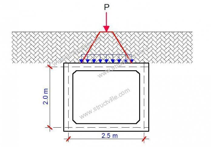
Typically, anyone who wishes to design box culverts should be very familiar with design loading for bridges. In the UK and European Union, the person should be familiar with BS 5400 Part 2 and EN 1992-2. This is because the traffic actions transferred to the members of a box culvert are very similar to that of bridges, and of course taking into account the peculiarities of box culverts due to the fact that they are usually buried under the ground. Hence, traffic actions such as wheel load is dispersed to the roof slab of the culvert as uniformly distributed load depending on the thickness of the earthfill.
The loadings on a box culvert according BS 5400:Part 2 and implemented by BD 37 are ;
(i) Permanent Loads
- Dead Loads
- Superimposed Dead Loads
- Horizontal Earth Pressure
- Hydrostatic Pressure and
- Buoyancy
- Differential Settlement Effects
(ii) Vertical Live Loads
- HA or HB loads on the
- carriageway
- Footway and Cycle Track Loading
- Accidental Wheel Loading
- Construction Traffic
(iii) Horizontal Live Loads
- Live Load Surcharge
- Traction
- Temperature Effects
- Parapet Collision
- Accidental Skidding
- Centrifugal Load
For the sake of this article, our attention will be on vertical wheel load dispersal on box culverts.
HA and HB Carriageway Loading
The nominal carriageway loading shall be HA or HB Loading as described in BD 37, whichever is the more onerous.
(a) HA Loading
(i) Where the depth of cover (H) is 0.6 m or less, HA loading shall consist of the HA UDL/KEL combination. No dispersion through the fill of either the HA UDL or the HA knife edge load shall be applied.
(ii) For cover depths exceeding 0.6 m, the HA UDL/KEL combination does not adequately model traffic loading. In these circumstances the HA UDL/KEL combination shall be replaced by 30 Units of HB loading, dispersed through the fill as described in paragraph (c) below.
(iii) Account shall also be taken of the single 100 kN HA wheel load, (dispersed through the fill as described in paragraph (c) below), where this has a more severe effect on the member under consideration than the loads described in (i) or (ii) above.
(b) HB Loading
(i) 45 Units of HB loading shall be applied on structures on Trunk Roads and Motorways. On structures on other Public Highways, 30 Units shall be applied unless a higher value is specified by the Overseeing Organisation.
(ii) A minimum of 30 Units of HB loading shall be applied to all structures including those that are designated to carry HA loading only.
(c) Dispersal of Wheel and Axle loads through the Fill
(i) All wheel loads shall be assumed to be uniformly distributed at ground level over a contact area, circular or square in shape, based on an effective pressure of 1.1N/mm2.
(ii) Dispersion of a wheel load through the fill may be assumed to occur both longitudinally and transversely from the limits of the contact area at ground level to the level of the top of the roof at a slope of 2 vertically to 1 horizontally as shown in Figure 2.3. Where the dispersion zones of the individual wheels overlap, they may be combined and distributed jointly as shown in Figure 2.3 (Zone 2). This applies to adjacent wheels on the same axle and to wheels on succeeding axles.
(iii) Where however any individual wheel is located close to the edge of the structure such that its 2:1 dispersal zone is curtailed by a headwall, the increase in pressure near to the headwall shall be taken into account. This may be done by assuming that the load is dispersed transversely over the curtailed width of the 2:1 dispersal zone.
(v) A wheel load not directly over the part of the structure being considered shall be included if its dispersion zone falls over the part of the structure.
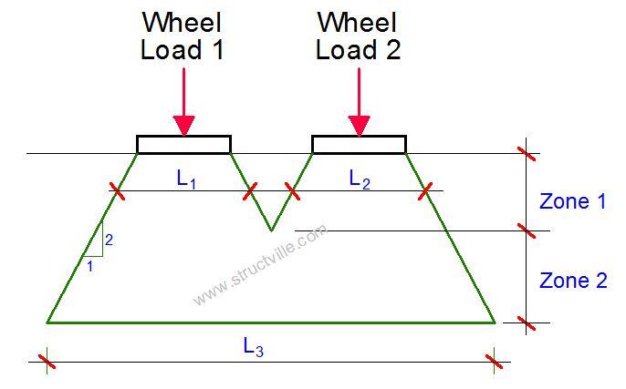
(d) Dispersal of the Wheel and Axle Loads through the Roof Slab.
Where the dispersed width of the wheel or axle at roof level is less than the spacing between adjacent joints (Lj), a further lateral dispersal of the load may be made at 45o down to the neutral axis of the roof slab (at depth hna) so that:
A single wheel is dispersed over a total width of C + H + 2hna
An axle is dispersed over a total width of C + (n-1)S + H + 2hna
where:
n is the number of wheels on an axle
S is the wheel spacing and
hna is the depth from the top of the roof to the neutral axis which may for convenience be approximated to half the overall roof depth.
Dispersion through the slab at 45o cannot occur through a longitudinal joint. The above approach does not account for the distribution properties of the structure itself.
Solved Example on Wheel Load Dispersal
Let us consider a box culvert with the dimensions shown below. The cover of thickness of earthfill above the culvert is 1.5 m. Obtain the wheel load distribution at the roof of the culvert.
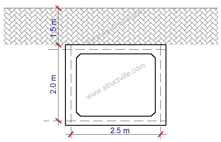
Since the thickness of the cover is greater than 0.6m, we shall consider 30 units of HB or single 100 kN HA load dispersed through the culvert, and then 45 units of HB. The most onerous will govern the design.
HA 100kN wheel load
Contact patch area to produce 1.1 N/mm2 = √(100000/1.1) = 302 × 302 mm
Using 2:1 rule, the load will be dispersed to the roof of the culvert as follows;
Dispersed area on top of box = 302 + [2 × (1500/2)] = 1802 × 1802 mm
Let us assume that the thickness of the roof slab is 300 mm, and assuming that the neutral axis is 150 mm;
Dispersed width to neutral axis of box = C + H + 2hna = 302 + 1500 + (2 x 150) = 2102 mm
Wheel load on dispersed area = 100/2.1022 = 22.632 kN/m2
45 units of HB load
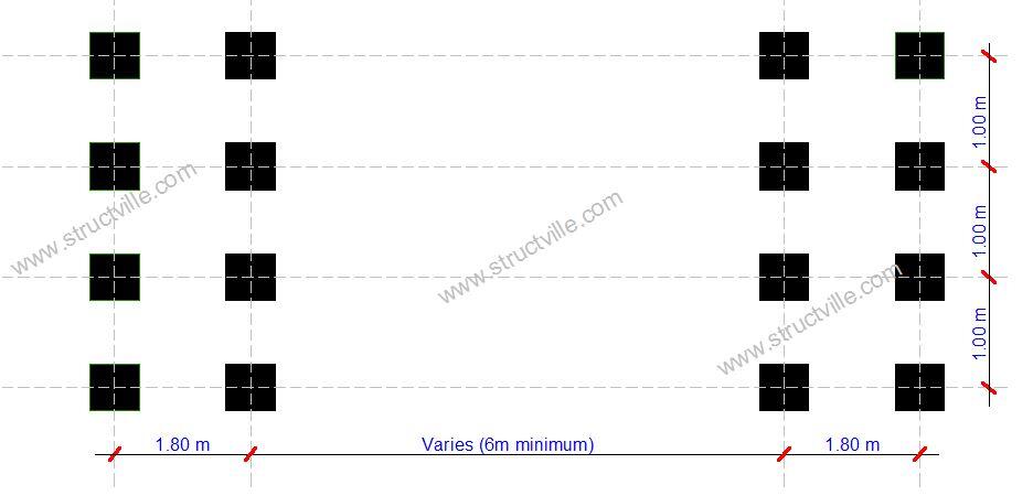
Wheel load = 45 × (10/4) = 112.5 KN
Contact patch area to produce 1.1 N/mm2 = √(112500/1.1) = 320 × 320 mm
Let us assume that there are no longitudinal joints in the structure. Therefore the code allows a transverse distribution down to the neutral axis of the roof slab (estimated as half the depth of the slab).
Depth from carriageway level to neutral axis of roof slab = 1500 + (300/2) = 1650 mm
In HB loading, 4 wheels on each axle are spaced at 1 m so, at 1:2 gradient, the transverse dispersal lines will overlap at a depth = 1000 – 320 = 680 mm < 1650 mm hence overlap and need to consider 4 wheels.
An axle is dispersed over a total width of C + (n-1)S + H + 2hna= 320 + (4 – 1) x 1000 + 1500 + 2(150) = 5120 mm
Alternatively;
Transverse dispersal of axle load = 3000 + 320 + (2 × 1500/2) + (2 × 300/2) = 5120 mm
Front and rear pair of axles are spaced at 1.8 m so, at 1:2 gradient, the longitudinal dispersal lines will overlap at a depth = 1800 – 320 = 1480 mm < 1650 mm hence we need to consider the front and rear pair of axles.
Longitudinal dispersal of axle load = C + (n-1)S + H + 2hna= 320 + (2 – 1) x 1800 + 1500 + 2(150) = 3920 mm
A little consideration will show that the dispersed length falls outside the width of the culvert, but we still go ahead to use it.
Axle load on dispersed area = 8 × 112.5 / (5.120 × 3.92) = 44.84 kN/m2
Therefore, HB loading is critical. This shows that value of 44.84 kN/m2 should be factored as appropriate, and applied on top of the culvert as a UDL for design purposes (depending on the load case of interest).






Great Work;
I want to know more about Below Statement Mathematically.
”Where however any individual wheel is located close to the edge of the
structure such that its 2:1 dispersal zone is curtailed by a headwall, the increase in pressure near to the headwall shall be taken into account”.
If for instance a vehicle wheel comes close to a headwall, and you find out that the anticipated pressure area (using 2:1 dispersal method) is reduced due to the headwall, you should use the increased pressure for your design.
Thanks for good work, there these culverts where there is no fill, how to apply Live Loads? i dont see it here
This is very good work Ubani, i’ve actually read another article you recently wrote on culverts again.
What would’ve happened if the Longitudinal dispersal lines for example didn’t overlap i.e. if the depth was greater than 1650mm.
Why laod dispersed at 2:1 and not otherwise??
Thanks for sharing.
Another educational piece.
Good article, would be nice to update the reference to HA HB loading to the new standard that supersedes BD 37 – now CS 454 sets ALL Model 1 and ALL Model 2