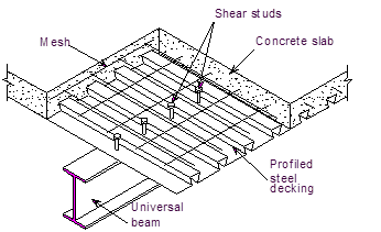
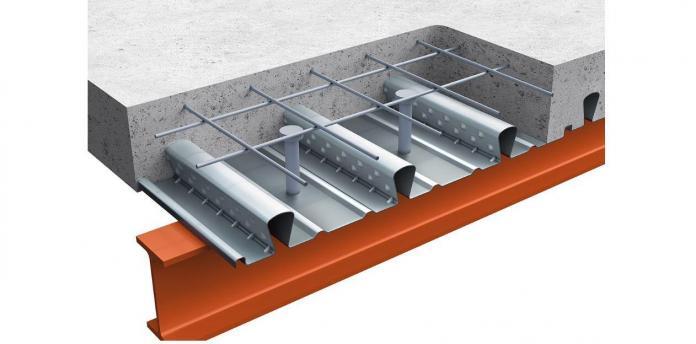
Composite slab with profiled metal decking provides economical solutions for floors of steel framed building systems. This is because they are easier to install, lighter in weight, and faster to execute when compared with precast, prestressed, and solid slab system for steel-framed buildings. The composite action of this floor system is achieved by welding steel studs to the top flange of the steel beams and embedding the studs in the concrete during concrete pouring.
Composite construction reduces frame loadings and results in a cheaper foundation system. Cold-formed thin-walled profiled steel decking sheets with embossments on top flanges and webs are widely used as the profiles. The use of this profiled metal decking eliminates the need for mat reinforcement in the slab and acts as the permanent shuttering for the concrete. Props are therefore not usually required during the process of concreting. This support scheme is usually suitable for spans that are less than 4m (spacing of the supporting beams). The supporting beams themselves can, however, span up to 12m.

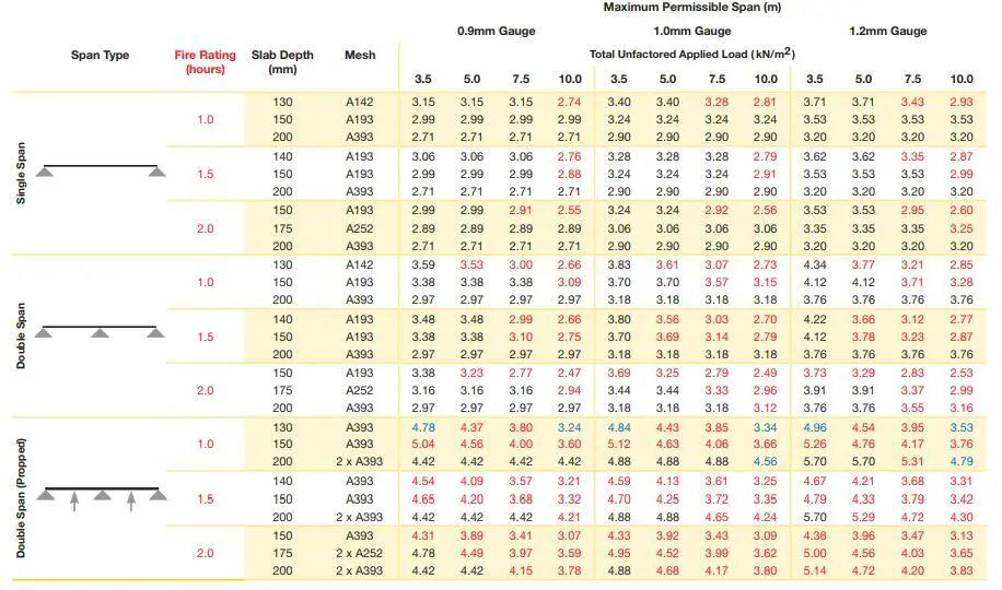
Structural engineers usually rely on load/span tables produced by metal deck manufacturers in order to determine the thickness of slab and mesh reinforcement required for a given floor arrangement, fire rating, method of construction, etc. The table below shows an example of a typical load/span table available from one supplier of metal decking.
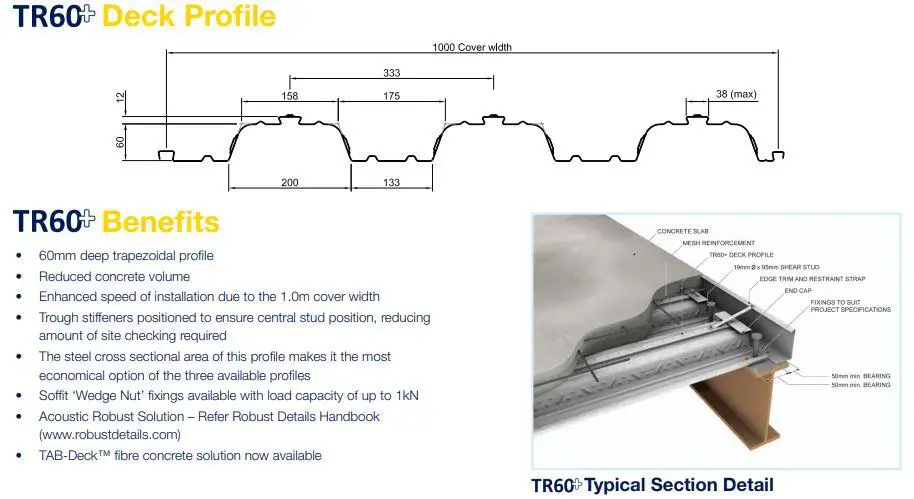
To download the full SMD technical data sheet for different types of profiled metal decking, click below.
Once the composite slab has been designed, the design of the primary and secondary composite beams (i.e. steel beams plus slab) can begin. This is normally carried out in accordance with the recommendations in Part 3: Section 3.1 of BS 5950. In Europe, composite sections are designed according to the requirements of Eurocode 4 (EN 1994 – 1- 1).
The steps in the design of profile metal decking for composite floors are;
- Determine the effective breadth of the concrete slab.
- Calculate the moment capacity of the section.
- Evaluate the shear capacity of the section.
- Design the shear connectors.
- Assess the longitudinal shear capacity of the section.
- Check deflection.
Design Example
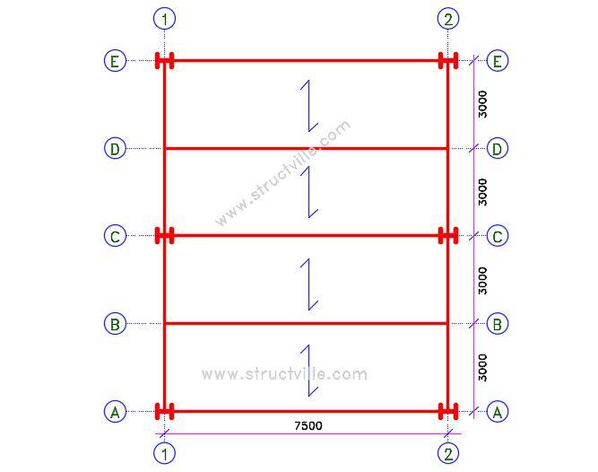
The figure below shows a part plan of a composite floor. The slab is to be constructed using profiled metal decking and normal weight, grade 30 concrete. The longitudinal beams are of grade S275 steel with a span of 7.5 m and spaced 3 m apart. Design the composite slab and verify the suitability of 406 x 178 x 67 UKB as the internal beams. The required fire-resistance is 1 hour.
Imposed load = 4 kN/m2
Partition load = 1 kN/m2
Weight of finishes = 1.2 kN/m2
Weight of ceiling and services = 1 kN/m2
Total applied load = 7.2 kN/m2 (to be used for slab design i.e. selection from manufacturer’s span-load table)
SLAB DESIGN
From the span-load table above, the configuration below will be satisfactory for the unpropped slab.
Beam span = 7.5 m
Beam spacing = 3.0 m
Total depth of slab hs = 130 mm
Depth of profile hp = 60 mm
Overall height of profile hd = 72 mm
Depth of concrete above profile = 58 mm
Profile: SMD TR60+ (1.2 mm gauge)
Gauge = 1.2 mm
Mesh: A142

From the manufacturer’s technical data sheet;
Volume of concrete = 0.096 m3/m2
Weight of concrete (wet) = 2.26 kN/m2
Weight of concrete (dry) = 2.21 kN/m2
Weight of profile = 0.131 kN/m2
Height to neutral axis = 33 mm
Shear connector
Connector diameter d = 19 mm
Overall welded height of hsc = 95 mm
Ultimate tensile strength fu = 450 N/mm2
Concrete
Normal weight C25/30 concrete
Cylinder trength fck = 25 N/mm2
Cube strength fck,cube = 30 N/mm2
Secant modulus of elasticity Ecm = 31 kN/mm2
Actions at Construction Stage
Permanent Actions
Self weight of sheeting = 0.131 kN/m2 x 3 m = 0.393 kN/m
Allowance for beam self-weight = 1.0 kN/m
Allowance for mesh = 0.05 kN/m2 x 3m = 0.15 kN/m
Total gk = 0.393 + 1 + 0.15 = 1.543 kN/m
Variable Actions
Self-weight of fresh concrete = 2.26 kN/m2 x 3m = 6.78 kN/m (note that fresh concrete is treated as variable action in the construction stage)
Construction load = 0.75 kN/m2 x 3m = 2.25 kN/m
Total qk = 6.78 + 2.25 = 9.03 kN/m
At ultimate limit state = 1.35gk + 1.5qk = 1.35(1.543) + 1.5(9.03) = 15.63 kN/m
Design moment MEd = ql2/8 = (15.63 x 7.52)/8 = 109.898 kNm
Design shear force VEd = ql/2 = (15.63 x 7.5)/2 = 58.61 kN
Actions at the composite stage
Permanent Actions
Self weight of sheeting = 0.131 kN/m2 x 3 m = 0.393 kN/m
Allowance for beam self-weight = 1.0 kN/m
Allowance for mesh = 0.05 kN/m2 x 3m = 0.15 kN/m
Self-weight of dry concrete = 2.21 kN/m2 x 3m = 6.63 kN/m
Weight of finishes = 1.2 kN/m2
Weight of ceiling and services = 1 kN/m2
Total gk = 0.393 + 1 + 0.15 + 6.63 + 1.2 + 1 = 10.373 kN/m
Variable Actions
Imposed load on floor = 4 kN/m2 x 3m = 12 kN/m
Movable partition allowance = 1 kN/m2 x 3m = 3 kN/m
Total qk = 12 + 3 = 15 kN/m
At ultimate limit state = 1.35gk + 1.5qk = 1.35(10.373) + 1.5(15) = 36.5 kN/m
Design moment MEd = ql2/8 = (36.5 x 7.52)/8 = 256.6 kNm
Design shear force VEd = ql/2 = (36.5 x 7.5)/2 = 136.875 kN
An advanced UK beam S275 is to be used for this design.
Fy = 275 N/mm2
γm0 = 1.0 (Clause 6.1(1) NA 2.15 BS EN 1993-1- 1:2005)
From steel tables, the properties of 406 x 178 x 67 UKB are;
Depth h = 409.4 mm
Width b = 178.8 mm
Web thickness tw = 8.8mm
Flange thickness tf = 14.3 mm
Root radius r = 10.2 mm
Depth between fillets d = 360.4 mm
Second moment of area y axis Iy = 24300 cm4
Elastic modulus Wel,y = 1190 cm3
Plastic modulus Wpl,y = 1350 cm3
Area of section A = 85.5 cm2
Height of web hw = h – 2tf = 380.8 mm
Es (Modulus of elasticity) = 210000 N/mm2 (Clause 3.2.6(1))
Check out also ….
Design of Steel Beams to BS 5950 – 1: 2000
Structural Analysis of Compound Arch-Frame Structure
Classification of section
ε = √(235/Fy) = √(235/275) = 0.92 (Table 5.2 BS EN 1993-1- 1:2005)
Outstand flange
Flange under uniform compression c = (b – tw – 2r)/2 = [178.8 – 8.8 – 2(10.2)]/2 = 74.8 mm
c/tf = 74.8/14.3 = 5.23
The limiting value for class 1 is c/tf ≤ 9ε = 9 × 0.92
5.23 < 8.28
Therefore, outstand flange in compression is class 1
Internal Compression Part (Web under pure bending)
c = d = 360.4 mm
c/tw = 360.4/8.8 = 40.954
The limiting value for class 1 is c/tw ≤ 72ε = 72 × 0.92 = 66.24
40.954 < 66.24
Therefore, the web is plastic. Therefore, the entire section is class 1 plastic.
Member Resistance Verification – Construction Stage
Moment Resistance
For the structure under consideration, the maximum bending moment occurs where the shear force is zero. Therefore, the bending moment does not need to be reduced for the presence of shear force (clause 6.2.8(2))
MEd/Mc,Rd ≤ 1.0 (clause 6.2.5(1))
Mc,Rd = Mpl,Rd = (Mpl,y × Fy)/γm0
Mc,Rd = Mpl,Rd = [(1350 × 275)/1.0] × 10-3 = 371.25 kNm
At the construction stage;
MEd/Mc,Rd = 109.898/371.25 = 0.296 < 1.0 Ok
Shear Resistance (clause 6.6.2)
The basic design requirement is;
VEd/Vc,Rd ≤ 1.0
Vc,Rd = Vpl,Rd = Av(Fy / √3)/γm0 (for class 1 sections)
For rolled I-section with shear parallel to the web, the shear area is;
Av = A – 2btf + (tw + 2r)tf (for class 1 sections) but not less than ηhwtw
Av = (85.5 × 10² – (2 × 178.8 × 14.3) + [8.8 + 2(10.2)] × 14.3 = 3854 mm2
η = 1.0 (conservative)
ηhwtw = (1.0 × 380.8 × 8.8) = 3351.04 mm2
3854 > 3351.04
Therefore, Av = 3854 mm2
The shear resistance is therefore;
Vc,Rd = Vpl,Rd = [3854 × (275/ √3)/1.0] × 10-3 = 612 kN
At the construction stage;
VEd/Vc,Rd = 58.61/612 = 0.095 < 1.0 Ok
Shear Buckling
Shear buckling of the unstiffnened web will not need to be considered if;
hw/tw ≤ 72ε/η
hw/tw = 380.8/8.8 = 43.27
72ε/η = (72 × 0.92)/1.0 = 66
43.27 < 66 Therefore shear buckling need not be considered.
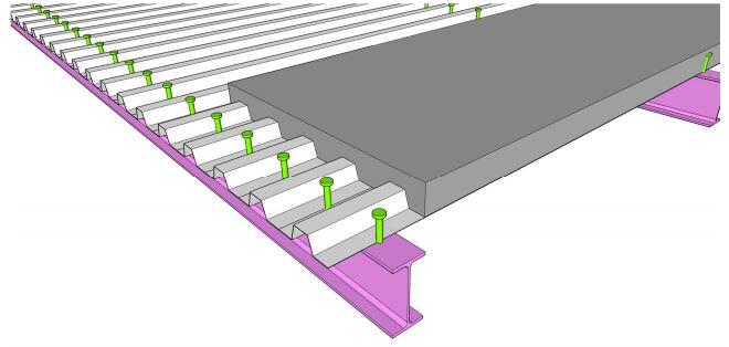
Design Resistance of Shear Connectors
Shear connector in a solid slab
The design resistance of a single headed shear connector in a solid concrete slab automatically welded in accordance with BS EN 14555 should be determined as the smaller of;
PRd = (0.8 x fu x π x 0.25d2)/γv (Clause 6.6.3.1(1) Equ(6.18) or
PRd = [0.29 x α x d2 x √(fck x Ecm)]/γv
Where;
α = 1.0 as hsc/d = 95/19 > 4 (Equation 6.21)
PRd = (0.8 x 450 x π x 0.25 x 192)/1.25 = 81.7 kN
PRd = [0.29 x 1.0 x 192 x √(25 x 31 x 103)]/1.25 = 73.7 kN
Shear connectors in profiled steel sheeting
For profiled sheeting with ribs running transverse to the supporting beams, PRd,solid should be multiplied by the following reduction factor;
kt = (0.7/√nr) x (b0/hp) x (hsc/hp – 1)

b0 = width of a trapezoidal rib at mid height of the profile = (133 + 175)/2 = 154 mm
hsc = 95 mm
hp = 60 mm
nr = 1.0 (for one shear connector per rib)
kt = (0.7/√1.0) x (154/60) x (95/60 – 1) = 1.0
Therefore PRd = ktPRd,solid = 1.0 x 73.7 = 73.7 kN
The design resistance per rib = nrPRd = 1 x 73.7 = 73.7 kN
Degree of shear connection
For composite beams in buildings, the headed shear connectors may be considered as ductile when the minimum degree of shear connection given in clause 6.6.1.2 is achieved.
For headed shear connectors with;
hsc ≥ 4d and 16mm ≤ d ≤ 25 mm
The degree of shear connection may be determined from;
η = Nc/Nc,f
Where;
Nc is the reduced value of the compressive force in the concrete flange (i.e. force transferred by the shear connectors)
Nc,f is the compressive force in the concrete flange at full shear connection (i.e. the minimum of the axial resistance of the concrete and the axial resistance of the steel)
For steel sections with equal flanges and Le < 25 m;
η ≥ 1 – (355/fy) x (0.75 – 0.03Le) where ≥ 0.4
Le = distance between points of zero moment = 7.5 m
η ≥ 1 – (355/275) x (0.75 – 0.03 x 7.5) = 0.322, therefore η = 0.4
Degree of shear connection present
To determine the degree of shear connection present in the beam, the axial resistances of the steel and concrete are required (Npl,a and Nc,f respectively)
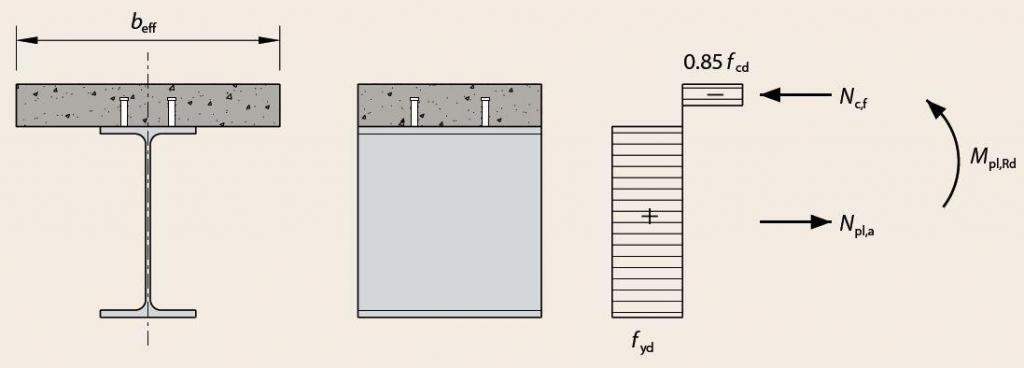
Determine the effective width of the concrete flange
At the mid-span, the effective width of the concrete falnge is;
beff = b0 + ∑bei
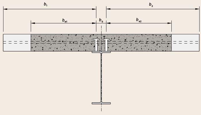
For nr = 1.0, b0 = 0 mm
bei = Le/8 but ot greater than bi
Le = 7.5 m (point of zero moment)
bi = distance from the outside shear connector to a point between adjacent webs. Therefore;
b1 = b2 = 1.5 m
be1 = be2 = Le/8 = 7.5/8 = 0.9375 m
The effective flange width is therefore
beff = b0 + be1 + be2 = 0 + 0.9375 + 0.9375 = 1.875 m = 1875 mm
Compressive resistance of the concrete flange
The design strength of the concrete fcd = 25/1.5 = 16.7 N/mm2
The TR60+ profile has a 12 mm deep re-entrant above the stiffener making the overall profile depth hd = 12 mm + 60 mm = 72 mm
The compressive resistance of the concrete flange is therefore;
Nc,f = 0.85fcdbeffhc = 0.85 x 16.7 x 1875 x 58 x 10-3 = 1543.7 kN
Tensile Resistance of the steel member
Npl,a = fy.A = 275 x 85.5 x 102 x 10-3 = 2351.25 kN
The compressive force in the concrete at full shear connection is the lesser. Therefore Nc = 1543.7 kN
Resistance of the shear connectors
n is the number of shear connectors present to the point of maximum bending moment. In this example, there are 7.5(2 x 0.333) = 12 ribs available for positioning shear connectors per half span.
Nc = n x PRd = 12 x 73.7 = 884.4 kN
The degree of shear connection present therefore is;
η = Nc/Nc,f = 884.4/1543.7 = 0.572 > 0.40 (Okay)
Design Resistance of the Cross-section at the composite stage
Bending Resistance
According to clause 6.2.1.2, the plastic rigid theory may be used for one connector per trough. With partial shear connection, the axial force in the concrete flange Nc is less than Npl,a (884.4 kN < 2351.25 kN). Therefore, the plastic neutral axis lies within the steel section. Assuming that the plastic neutral axis lies a distance xpl below the top of the flange of the section, where;
xpl = (Npl,a – Nc)/2fyb = (2351.25 – 884.4)/(2 x 275 x 178.8) = 0.0149 m = 14.916 mm > tf (14.3 mm)
Therefore the plastic neutral axis lies below the top flange.
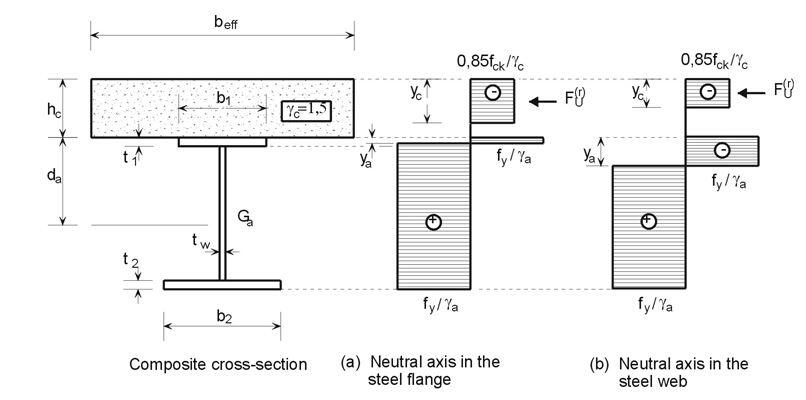
yc = Nc/[0.85fckbeff /γc] ≤ hc
yc = (884.4 x 1000)/[0.85 x 25 x 1875/1.5] = 33.28 mm
MRd = Nc(hc + da – yc/2) + 2btffy(da – tf/2) + tw(ya – tf)(fy)(2da – ya – tf)
MRd = (884.4 x 103) x (130 + 204.7 – 33.28/2) + 2 x 178.8 x 14.3 x 275 x (204.7 – 14.3/2) + 8.8(14.92 – 14.3) x 275 x (2 x 204.7 – 14.92 – 14.3) = 559669744.2 Nmm = 559.669 kNm
MEd = 256.6 kNm
MEd/MRd = 256.6/559.669 = 0.458 < 1.0 (Okay)
Shear Resistance at the Composite Stage
The shear resistance is therefore;
Vc,Rd = Vpl,Rd = [3854 × (275/ √3)/1.0] × 10-3 = 612 kN
VEd = 136.875 kN
VEd/Vc,Rd = 136.875/612 = 0.223 < 1.0 Ok
Longitudinal shear resistance of the slab
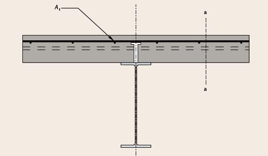
Neglecting the contribution of the steel, we ned to verify that;
Asffsd/Sf > vEdhf/cotθ
Where;
vEd is the design longitudinal shear stress in the concrete slab
fsd is the design yield strength of the reinforcing mesh = 0.87fyk = 0.87 x 500 = 434.8 N/mm2
hf = depth of the concrete above the profiled sheeting = 70 mm
θ angle of failure (try 26.5o)
Asf/Sf = At (for the plane of failure shown as section a-a)
At is the cross-sectional area of transverse reinforcement mm2/m)
The verification equation therefore becomes;
Atfyd > vEdhf/cotθ
The required area of tensile reinforcement At must satisfy the following;
At > vEdhf/fydcotθ
The longitudinal shear stress is given by;
vEd = ∆Fd/hf∆x
Where;
∆x is the critical length under consideration, which is usually taken as the distance between the maximum bending moment and the support = L/2 = 7.5/2 = 3.75m
∆Fd = Nc/2 = 884.4/2 = 442.2 kN
vEd = ∆Fd/hf∆x = (442.2 x 10³)/(70 x 3750) = 1.68 N/mm2
vEdhf/fydcotθ = (1.68 x 70)/(434.8 x cot 26.5o) = 0.134 mm2/mm
For the arrangement, the area of tensile reinforcement required is 134 mm2/m
Therefore A142 mesh provided is adequate (Asprov = 142 mm2/m)
Crushing of the concrete flange
It is important to verify that
vEd < vfcdsinθfcosθf
v = 0.6(1 – fck/250) = 0.6 x (1 – 25/250) = 0.54
vfcdsinθfcosθf = 0.54 x 16.67 x sin(26.5) x cos(26.5) = 3.59 N/mm2
(vEd) 1.68 N/mm2 < 3.59 N/mm2 (Okay)
Serviceability limit state
Modular ratios
For short term loading, the secant modulus of elasticity should be used. Ecm = 31 kN/mm2. This corresponds to a modular ratio of;
n0 = Es/Ecm = 210/31 = 6.77 (clause 5.4.2.2)
For long term loading;
nL = n0(1 + ψLϕt)
Where ψL is the creep multiplier taken as 1.1 for permanent loads and ϕt is the creep coefficient taken as 3.0.
nL = 6.77 x (1 + 1.1 x 3) = 29.11
When calculating deflection due to variable action, the modular ratio is taken as;
n = 0.333nL + 0.667n0 = 0.333(29.11) + 0.667(6.77) = 14.22
Since the beam is simply supported, use the gross value of second moment of area, Ic, of the uncracked section to calculate deflection.
Ic = Iy + [beff(hs – hp)3/12∙ni] + [A∙beff(hs – hp)(h + hs + hp)2]/4[A∙ni + beff(hs – hp)]
For n0 = 6.77
Ic = 24300 x 104 + [1875(130 – 60)3/(12 x 6.77)] + [85.5 x 102 x 1875(130 – 60) x (409.4 + 130 + 60)2]/4[85.5 x 102 x 6.77 + 1875(130 – 60)] = 78385 x 104 mm4
For nL = 29.11
Ic = 24300 x 104 + [1875(130 – 60)3/(12 x 29.11)] + [85.5 x 102 x 1875(130 – 60) x (409.4 + 130 + 60)2]/4[85.5 x 102 x 29.11 + 1875(130 – 60)] = 50999 x 104 mm4
For n = 14.22
Ic = 24300 x 104 + [1875(130 – 60)3/(12 x 14.22)] + [85.5 x 102 x 1875(130 – 60) x (409.4 + 130 + 60)2]/4[85.5 x 102 x 14.22 + 1875(130 – 60)] = 64543 x 104 mm4
Deflection due to actions on the steel at the construction stage;
Actions = self weight of fresh concrete + mesh + sheeting + steel section
w1 = 5gl4/384EI = (5 × 8.323 × 75004)/(384 × 210000 × 24300 × 104) = 6.719 mm
Deflection due to permanent action on the steel at the composite stage;
Actions = weight of finishes + ceiling and services
w2 = 5gl4/384EI = (5 × 6.6 × 75004)/(384 × 210000 × 50999 x 104) = 2.54 mm
Deflection due to variable action on the steel at the composite stage;
Actions = Imposed load + partition allowance
w3 = 5ql4/384EI = (5 × 15 × 75004)/(384 × 210000 × 64543 x 104) = 4.559 mm
Total deflection = w1 + w2 + w3 = 6.719 + 2.54 + 4.559 = 13.818 mm
Allowable deflection = L/360 = 7500/360 = 20.833 mm.
13.818 < 20.833 Therefore deflection is okay.



Good morning Engineer Ubani. How can I purchase a copy of the publication on profile metal deck
Hi Engr. Mike. Kindly send an e-mail to info@structville.com
Thanks.
This is such a nice blog on designing profiled metal deck composite slabs.This article makes the work straight and easy for us. It is a wonderful article. It is very useful article and would suggest others too. I am sure many people will come to read this in future. One must check this https://www.dukeswiremesh.com/ it gives us more info on this topic.
very interesting , please give more details on calculation