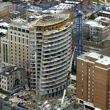
The bracing system (stabilising components) of a high-rise building is normally made up of different units: frameworks (beams and columns), shear walls, coupled shear walls, and cores. They all contribute to the overall lateral load resistance of the system, but their contributions can be very different both in weight and in nature, so it is essential for the designer to know their behaviour in order that the optimum bracing system can be produced [1].
Bracing components in a building are assumed to be fully fixed at the base and hinged at the top. Non-stabilising elements are assumed to be hinged at both ends. Since non-stabilising elements must be braced by stabilising elements, they have a negative contribution to load resistance [2].
The different types of stabilising components (bracing elements) in a building are;
- Columns and frameworks
- Shear walls
- Towers and cores
Columns and frameworks
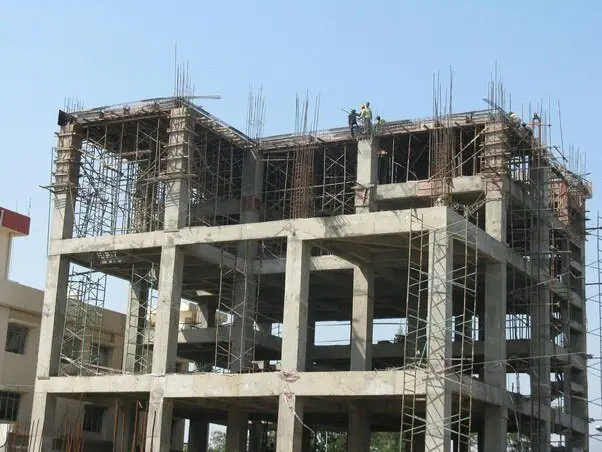
A linear structural member which takes vertical compressive loads can generally be called a column. Columns can be constructed of steel, wood, or reinforced concrete depending on the strength and/or the aesthetics required. Columns are found mainly in structures in order to provide support for beams or slabs.
When calculating stability in a structure with columns it is essential to ascertain if the column is stabilising or not [2]. This means that non-stabilising elements have to be held up by the stabilising elements so they have a certain negative effect on the overall stiffness of the system.
The behaviour of frameworks under lateral load is complex, mainly because they develop both bending and shear deformations when resisting lateral loads [1]. Due to the complexity of the problem, designers and researchers have made considerable efforts to develop approximate techniques and methods. Perhaps the best and most widespread method is the continuum method which is based on an equivalent medium that replaces the framework [1]. However, due to the availability of numerous commercial computer programs for finite element analysis, this computational challenge has largely been overcome.
Columns and frameworks alone are not suitable for resisting lateral loads once the building exceeds 10 storeys, and must be combined with shear walls and cores.
Shear walls
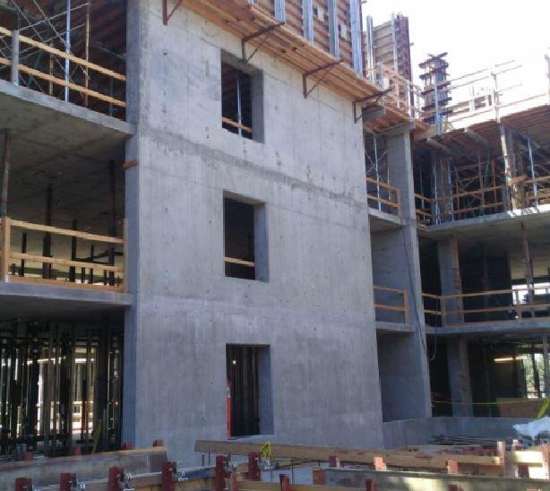
Shear walls, made of reinforced concrete, are used in modern buildings because of their effectiveness in maintaining stability and for the freedom they offer the architect who is designing [3]. Shear walls are stiff in the direction of the wind and can be effectively utilised in resisting the internal stresses due to wind action. A shear wall’s position in a building is often initially decided by the architect.
An architect is trained to design for the building’s function and appearance and not for its stability. Therefore, when a structural engineer is not involved in the first phase of design, it may lead to the shear walls being situated in non-favourable positions [2].
Also, while choosing reinforced concrete walls as partition walls, the architect can be unintentionally gaining stabilising elements. Pierced shear walls or coupled shear walls are described as shear walls with holes. These holes can be windows or doors that are necessary for access or lighting for the building. The force from the horizontal wind load results in shear forces which act within the wall and tension and compression resulting at the ground.
Towers/Cores
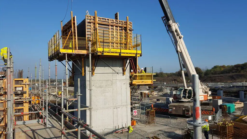
Towers are rigid cores situated inside tall buildings. Shear walls are often built together to create three-dimensional units. A good example is the U-shaped elevator core but many different shapes exist in building structures. The second moments of area of a reinforced concrete core are normally large and a small number of cores are often sufficient to provide the building with the necessary stiffness to resist lateral loading [1].
Usually, a core will exist with another core or combined with shear walls and/or with columns. The combined effect will give rise to greater resistance to torsion depending on how the units are situated in relation to each other. Ideally, they are situated as far apart as possible for creating a torsional resistance. A disadvantage with using a single core, on its own, is that it is susceptible to torsion and must therefore be heavily dimensioned in order to resist torque [2].
The use of cores is however favourable in that they can be used not only as stabilising units but also as elevator shafts or stairwells. Funnelling of ventilation shafts, water pipes and electric cables can also be hidden within the tower giving the architect more manoeuvrability and the client more effective use of the space provided. Towers which have open cross sections, for example U-shaped or H-shaped, have less resistance to torsion than closed sections and should, in general, be combined with other stabilising components.
References
[1] Zalka K. A. (2013): Structural Analysis of Regular Multi-storey Buildings. CRC Press – Taylor and Francis Group, USA
[2] Gustaffson D., and Hehir J. (2005): Stability of tall buildings. M.Sc thesis submitted to the Department of Civil and Environmental Engineering, Chalmers University of Technology, Sweden
[3] Aginam C.H., Chidolue C.A., and Ubani O.U. (2015): Effect of Planar Solid shear wall-frame arrangement on the deformation behaviour of multi-story frames. IOSR Journal of Mechanical and Civil Engineering 12(1):98-105

