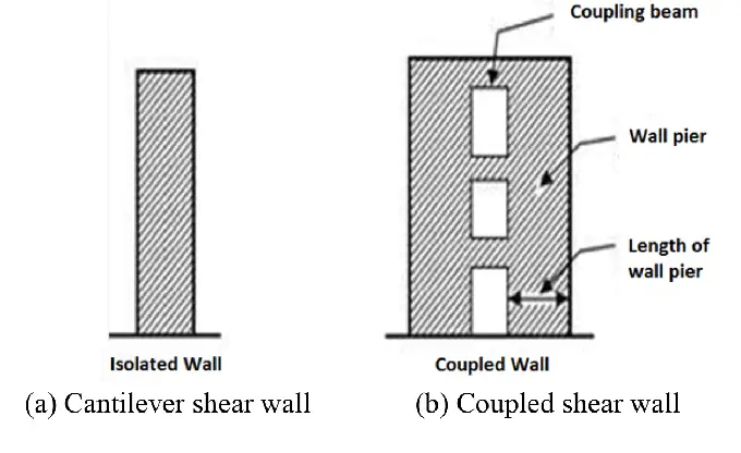
When two shear walls are connected intermittently with rigid beams or links, a coupled shear wall structure is formed. In coupled shear walls, the structural response of the two shear walls is linked to each other, influenced by the stiffness of the connecting beams. Coupled shear walls have found a variety of applications in the design of tall buildings, and other earthquake-resistant structural systems.
The effect of wind becomes more influential as a building gets taller. To effectively resist the force from wind, shear walls, frames, or a combination of both structural forms are normally employed in tall buildings. When shear walls have openings (pierced) which may serve for aesthetic, lighting or ventilation purposes, the behaviour of the shear wall is coupled to some degree.
The coupling beams, which connect the shear walls, play a crucial role in the behaviour of coupled shear walls. These beams are specifically designed to exhibit ductile inelastic behaviour, meaning they can undergo significant deformation without failure. This ductility allows them to dissipate energy during seismic events, effectively absorbing and distributing the lateral forces throughout the structure.

Furthermore, the dissipation of energy in coupled shear walls relies on the yield moment capacity and plastic rotation capacity of the coupling beams. When the yield moment capacity is excessively high, the beams experience limited rotations and dissipate minimal energy. Conversely, if the yield moment capacity is too low, the beams may undergo rotations exceeding their plastic rotation capacities.
Consequently, it is very important to design the coupling beams to have an optimal level of yield moment capacities, which are contingent upon the available plastic rotation capacity in the beams.
Advantages of Coupled Shear Walls over Planar Shear Walls
The arrangement of coupled shear walls provides several advantages over regular shear walls or other lateral load-resisting systems:
- Enhanced stiffness: The coupling of multiple shear walls significantly increases the overall stiffness of the structure, reducing lateral deflections and sway during wind or seismic events.
- Improved load distribution: The coupling beams ensure a more even distribution of lateral loads across the shear walls, preventing localized stress concentrations and improving the overall load-carrying capacity of the system.
- Architectural flexibility: Coupled shear walls offer architectural flexibility, allowing for larger open spaces and creative designs, as the lateral stability is not solely dependent on the positioning of walls.
- Seismic resilience: The ductile behaviour of the coupling beams helps dissipate seismic energy, making coupled shear walls particularly effective in earthquake-prone regions, where they can significantly enhance a building’s seismic resilience.
- Cost-effectiveness: Compared to other lateral load-resisting systems like moment frames or braced frames, coupled shear walls can provide a cost-effective solution while still offering excellent performance
This aericle explores the wind load analysis of coupled shear wall structures with a fully solved example, under the following assumptions;
(i) The entire wind load is transferred to the shear walls (the contribution of the frames have been neglected)
(ii) The wind load acts as a uniformly distributed force of F/H
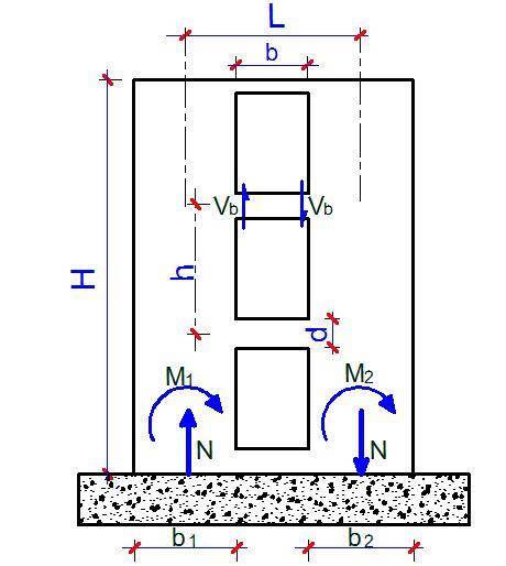
The two main parameters that define the behaviour of pierced shear walls are alpha(α) and beta (β), which depend on the geometrical properties of the coupling/connecting media (beams or floor slabs) and the shear wall. For fairly symmetrical arrangements as shown below, the following relationships given below can be used for the purpose of analysis.
N/B: This is a curtailed information; kindly consult specialist textbooks/publications for full knowledge of the subject.
The value of Kv can be obtained from the table below;
Solved Example
The structural arrangement of a tall building is shown below. The building is 90m tall, with 30 storeys @3m storey height. We are to determine the internal forces induced in the shear walls due to the wind load.
Building Data:
Height of building (H) = 90m
Storey height (h) = 3m
Thickness of shear wall (t) = 0.35m
Depth of connecting beam (d) = 900mm
Width of opening (b) = 2500mm
Centreline of connected walls (L) = 8000mm
Basic wind speed = 40 m/s
Wind Load Analysis (Eurocode 1 Part 4)
(a) Basic wind velocity
The fundamental value of the basic wind velocity Vb,0 is the characteristic 10-minute mean wind velocity irrespective of wind direction and time of the year, at 10 m above ground level in open-country terrain with low vegetation such as grass, and with isolated obstacles with separations of at least 20 obstacle heights.
The basic wind velocity Vb,0 is calculated from;
Vb = Cdir .Cseason .Vb,0
Where:
Vb is the basic wind velocity defined as a function of wind direction and time of the year at 10m above the ground of terrain category II
Vb,0 is the fundamental value of the basic wind velocity
Cdir is the directional factor (defined in the National Annex, but recommended value is 1.0)
Cseason is the season factor (defined in the National Annex, but recommended value is 1.0)
For the area and location of the building that we are considering;
Basic wind velocity Vb,0 = 40 m/s
Vb = Cdir .Cseason . Vb,0 = 1.0 × 1.0 × 40 = 40 m/s
(b) Mean Wind
The mean wind velocity Vm(z) at a height z above the terrain depends on the terrain roughness and orography, and on the basic wind velocity, Vb, and should be determined using the expression below;
Vm(z) = cr(z). co(z).Vb
Where;
cr(z) is the roughness factor (defined below)
co(z) is the orography factor often taken as 1.0
The terrain roughness factor accounts for the variability of the mean wind velocity at the site of the structure due to the height above the ground level and the ground roughness of the terrain upwind of the structure in the wind direction considered. Terrain categories and parameters are shown in the table below;
cr(z) = kr. In (z/z0) for zmin ≤ z ≤ zmax
cr(z) = cr.(zmin) for z ≤ zmin
Where:
Z0 is the roughness length
Kr is the terrain factor depending on the roughness length Z0 calculated using
Kr = 0.19 (Z0/Z0,II )0.07
Where:
Z0,II = 0.05m (terrain category II)
Zmin is the minimum height
Zmax is to be taken as 200 m
Kr = 0.19 (0.05/0.05)0.07 = 0.19
cr(z) = kr. In (z/z0) = 0.19 × In(90/0.05) = 1.424
Therefore;
Vm(90) = cr(z).co(z).Vb = 1.424 × 1.0 × 40 = 56.96 m/s
(c) Wind turbulence
The turbulence intensity Iv(z) at height z is defined as the standard deviation of the turbulence divided by the mean wind velocity. The recommended rules for the determination of Iv(z) are given in the expressions below;
Iv(z) = σv/Vm = k1/(c0(z).In(z/z0)) for zmin ≤ z ≤ zmax
Iv(z) = Iv.(zmin) for z ≤ zmin
Where:
kI is the turbulence factor of which the value is provided in the National Annex but the recommended value is 1.0
Co is the orography factor described above
Z0 is the roughness length described above.
For the building that we are considering, the wind turbulence factor at 90m above the ground level;
Iv(90) = σv/Vm = k1 / (c0 (z).In (z/z0)) = 1/(1 × In(90/0.05) ) = 0.1334
(d) Peak Velocity Pressure
The peak velocity pressure qp(z) at height z is given by the expression below;
qp(z) = [1 + 7Iv(z)] 0.5.ρ.Vm2(z)= ce(z).qb
Where:
ρ is the air density, which depends on the altitude, temperature, and barometric pressure to be expected in the region during wind storms (recommended value is 1.25kg/m3)
ce(z) is the exposure factor given by;
ce(z)= (qp(z))/qb
qb is the basic velocity pressure given by;
qb = 1/2.ρ.Vb2
qp(90m) = [1 + 7(0.1334)] × 1/2 × 1.25 × 56.962 = 3921.313 N/m2
Therefore, qp(90m) = 3.921 kN/m2
(e) Wind Pressure Coefficient
h/d = 90/22.5 = 4
Pressure coefficient for windward side (zone D) = +0.8
Pressure coefficient for leeward side (zone E) = -0.65 (from linear interpolation)
Net pressure coefficient = 0.8 – (-0.65) = 1.45
According to clause 7.2.2(2), the force generated from zone D and E simultaneously should be corrected for lack of correlation.
Since h/d = 4 in our calculation, we have to interpolate between h/d ≥ 5(1.0) and h/d ≤ 1.0 (0.85).
On interpolating;
Correction factor = 0.9625
Therefore, net wind pressure = 0.9625 × 1.45 × 3.921 = 5.472 kN/m2
IV Structural Analysis
The wind force of the structure;
F = 5.472 kN/m2 × 24m × 90m = 11819.52 kN (taking structural factor as 1.0 because building is less than 100m tall, and h/d = 4)
If we assume that this load is shared equally among the two shear walls, then the load on each shear wall = 5909.76 kN
Geometrical Properties of Elements
Area of shear walls = A1 = A2 = 0.35 × 5.5 = 1.925 m2
Second moment of area of walls = I1 = I2 = (0.35 × 5.53)/12 = 4.852 m4
Moment of inertia of connecting beam Ib = (0.35 × 0.93)/12 = 0.02126 m4
be = (2b + 5d)/3 = [(2 × 2.5) + (5 × 0.9)] / 3 = 3.167
αH = 19.962
Therefore, the axial force (N) at the bottom of wall;
The bending moment at the bottom of the wall elements;
The shear force at the connecting beams;
The bending moment on the connecting beams;
These internal forces should be factored, and combined with other appropriate load cases for the purpose of design.
Thank you for reading.
Join our Facebook page for more at
www.facebook.com/structville


which textbook actually explains wind loading comprehensively pls be of help
There are lot of textbooks that offer dedicated topics on wind load analysis. First of all get the code of practice, then textbooks like Reynolds, Steedman and Threlfall can broaden your knowledge on application of wind load. You can also search random topics on Google
Hey very cool web site!! Man .. Beautiful .. Wonderful .. I will bookmark your website and take the feeds additionally?I am happy to find a lot of helpful information here within the put up, we need work out extra techniques on this regard, thanks for sharing. .
CoBie adaptation in USA
Interference Analysis in USA
MEP F modelling in USA
Revit Modeling in USA
Fabrication Drawings preparation in USA
Shop Drawings Preparation in USA
Structural Analysis in USA