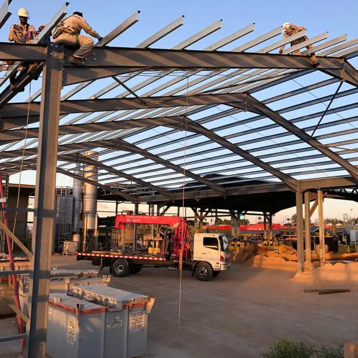
Buildings with large spans can be economically constructed using steel portal frames. Such structures are very common in business parks, industrial complexes, warehouses, places of worship, leisure houses, and sports complexes. The functionality of these types of buildings is usually influenced by factors such as the usage of the building, property development laws, availability of space, development plan, and the desired quality of the finished building.
Portal frames are characterized by their unique structural configuration and rigid connections. They comprise two vertical or inclined columns, rigidly connected at their eaves by a horizontal or inclined beam called the rafters. This arrangement forms a rigid frame that is either rectangular or trapezoidal in profile, with inherent in-plane stability.
The design of portal frames involves the selection of adequate column and rafter steel sections that will satisfy critical performance criteria such as bending, shear, axial compression, flexural buckling, lateral torsional buckling, and deflection, under the anticipated loading conditions.
In portal frames, the beam or rafters act as a portal, effectively transferring gravity and wind loads to the columns. Typically, a rigid bolted end-plate connection facilitates this load transfer and plays a critical role in the overall stability of the frame. The columns can be supported as fixed or pinned members connected to the base plates. When the columns are supported as fixed connections, moment-resisting base plate design will need to be carried out.
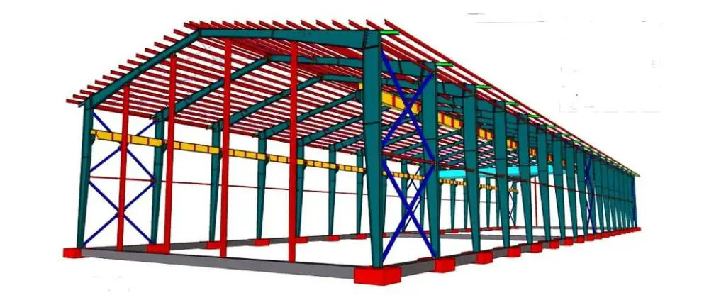
Steel as a construction material offers numerous possibilities to achieve both pleasant and flexible functional use economically.
Portal frames with hinged column bases are the most common type of industrial building and are used all over Nigeria and the rest of the world. Portal frames possess adequate stability in-plane and majorly require bracing for out-of-plane stability. Other structural forms that can also be used in industrial frames are lattice trusses, cable-stayed structures, etc.
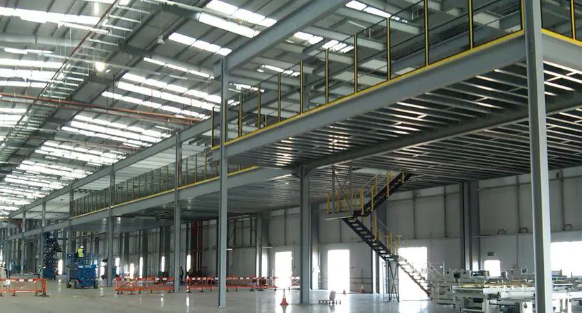
As a structure designed to accommodate complex human activities, it is very important to pay adequate attention to the details that will make the building functional, aesthetically pleasing, safe, and efficient. Expertise in the area of human factor engineering should be employed to make every aspect of the building efficient. The general aspects that should be considered before the detailed design of an industrial building are;
- Space optimization.
- Speed of construction.
- Access and security.
- Flexibility of use.
- Environmental performance.
- Standardization of components.
- Infrastructure of supply.
- Service integration.
- Landscaping.
- Aesthetics and visual impact.
- Thermal performance and air-tightness.
- Acoustic insulation.
- Weather-tightness.
- Fire safety.
- Design life.
- Sustainability considerations.
- End of life and re-use
Loadings on Portal Frames
Steel portal frames designed and constructed in Europe typically follow the guidance set out in the Eurocodes (EC). These are a series of harmonized standards that define the requirements for the safety and serviceability of structures. Here’s a breakdown of the anticipated loadings considered according to the Eurocodes for steel portal frames:
Permanent Actions
- Dead loads: This includes the self-weight of the steel frame itself, cladding materials (roofing, wall panels), any permanent fixtures or suspended ceilings.
- Superimposed dead loads: These are permanent loads that are not part of the structure itself but add weight. Examples include partitions, fixed building services (HVAC units, piping), and permanent building equipment.
Variable Actions
- Snow loads: The weight of snow accumulation on the roof, determined based on the geographical location and specific snow load zone.
- Wind loads: Wind pressure acting on the entire structure, considering the building’s shape, size, and location. Both positive (wind suction) and negative (wind pressure) wind loads are evaluated.
- Imposed loads: These are live loads acting on the structure due to occupancy or use. The specific value depends on the building function (residential, office, storage) and any specific use cases.
- Seismic loads: In seismic zones, earthquake loads are considered to ensure the structure can withstand potential earthquake forces. The specific design approach depends on the seismic hazard level of the location.
Combination of Actions
The Eurocodes also require considering various combinations of these actions for design. This accounts for the possibility of multiple loads acting simultaneously. Specific factors are applied to each action type depending on whether it’s a permanent, variable, or accidental load. This ensures the design considers realistic scenarios the structure might encounter.
Methods of Portal Frame Analysis
Two primary approaches can be adopted for analyzing portal frame structures. They are:
- elastic analysis, and
- plastic analysis.
Elastic Analysis
The elastic analysis approach is based on the assumption that the frame exhibits purely elastic behaviour, meaning it does not experience any permanent deformations beyond its elastic limit when subjected to loading.
When a portal frame undergoes gravity loading, the bending moment reaches its peak values at the eaves (the horizontal line where the roof meets the wall) and at the apex (the highest point of the frame). At the eaves, the bending moment exhibits a hogging behaviour (convexity upwards), while at the apex, it displays a sagging behaviour (convexity downwards).
Elastic analysis tends to yield higher maximum bending moments at both the eaves and apex compared to plastic analysis. Consequently, design based solely on elastic analysis often results in less economical frames, as it necessitates the use of larger and potentially more expensive members to accommodate these higher moments.
Plastic Analysis
In contrast to elastic analysis, plastic analysis of portal frames acknowledges the potential for inelastic deformations within the structure. This allows for a more significant redistribution of bending moments throughout the structure. This redistribution is facilitated by the formation of plastic hinges at specific locations within the frame.
These plastic hinges typically develop at sections where the bending moment reaches the material’s plastic moment resistance, signifying the point at which the material yields. As a result of this redistribution, plastic analysis often leads to the design of lighter and more economical portal frames compared to those solely based on elastic analysis.
Second Order Effects in Portal Frames
While plastic analysis offers a more realistic representation of portal frame behaviour compared to elastic analysis, it is essential to acknowledge that neither method explicitly incorporates the influence of the frame’s stability under load, also known as the second-order effect. This is particularly relevant for portal frames, which are typically slender and lightweight structures susceptible to experiencing significant deformations under load. As a consequence, they are inherently more prone to these second-order effects.
To address this critical aspect, BS EN 1993-1-1 Clause 5.2.2 provides a comprehensive framework encompassing various methodologies for accounting for second-order effects during the design and analysis of steel structures. Furthermore, Clause 5.2 of the same standard establishes well-defined criteria to assist engineers in determining the significance of second-order effects in specific steel structures.
In the context of portal frame structures, a critical parameter known as αcr is employed to assess the frame’s sensitivity to second-order effects. This factor represents the ratio between the structure’s elastic critical buckling load (Fcr) for global instability and the applied design load (FEd). When αcr meets or exceeds a value of 10 for elastic analysis, second-order effects are generally considered negligible.
αcr = Fcr/FEd ≥ 10
However. BS EN 1993-1-1 has a simple approximate method to evaluate αcr when the roof slope is less than 26° and the axial force in the rafter is not significant. The axial force in the rafter is significant if NEd ≥ 0.09Ncr
The buckling amplification factor αcr can be calculated using the relationship below;
αcr = h/(200 × δNHF)
Where;
h is the height to the eaves
δNHF is the horizontal deflection at the eaves under a notional horizontal force applied at each eaves node, equal to 1/200 of the factored vertical base reaction.
Member Stability Analysis
Portal frames are typically constructed from open steel sections and are susceptible to a specific buckling mode known as lateral-torsional buckling. This phenomenon occurs when the member experiences combined bending and twisting deformations. To mitigate this risk, it is often necessary to incorporate various restraint mechanisms within the frame.
Both the rafters (horizontal beams) and columns (vertical supports) in a portal frame require careful evaluation to ensure they possess adequate stability against buckling. To address this challenge, three primary categories of restraints can be employed in portal frames:
- Lateral Restraint: As the name suggests, lateral restraints primarily focus on preventing lateral movement of the compression flange. This is often achieved through:
- Purlins or Side Rails: These horizontal or slightly inclined members, when securely connected to the top flange of the rafter, act as a barrier against lateral movement, particularly when the compression flange is on the top side of the rafter.
- Torsional Restraint: This type of restraint aims to prevent the entire member (rafter or column) from twisting about its longitudinal axis. It typically involves a combination of:
- Purlins or Side Rails: Similar to lateral restraints, purlins or side rails can contribute to torsional restraint when used in conjunction with:
- Rafter or Column Stays: These are additional steel members that connect the flange experiencing compression (typically the top flange of a rafter) to a more stable structural element, like a column or another rafter. The stay effectively restricts the twisting motion.
- Purlins or Side Rails: Similar to lateral restraints, purlins or side rails can contribute to torsional restraint when used in conjunction with:
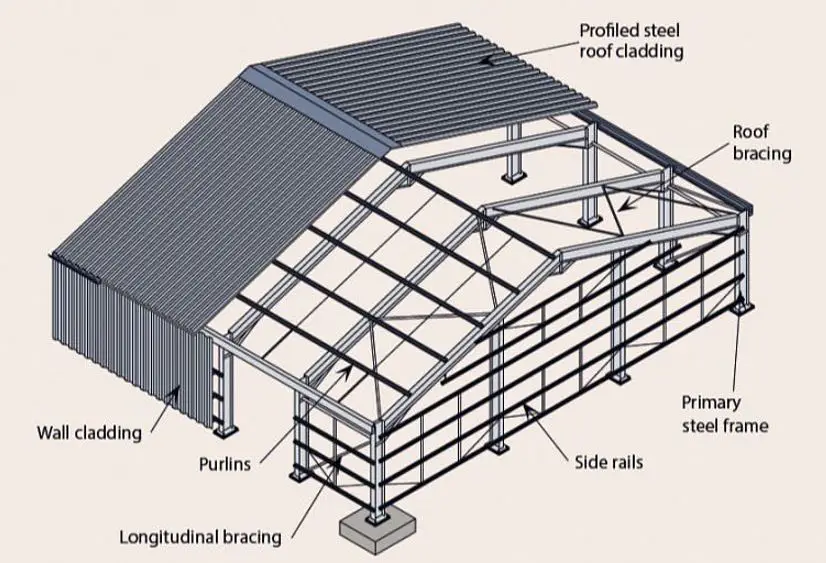
Intermediate Restraints
An additional concept to consider is the use of intermediate restraints. These can also be purlins or side rails, but strategically placed between the primary torsional restraints. Their primary function is to provide lateral support to the tension flange (typically the bottom flange of a rafter) when it’s experiencing tension. This allows for increased spacing between the more robust torsional restraint systems, potentially offering a more economical design.
The choice of the most suitable restraint system depends on several factors, including:
- Span length: Longer spans generally necessitate more robust restraints, like closely spaced purlins or combined torsional restraint systems.
- Loading conditions: Heavier loads require stronger restraints to maintain stability.
- Cost and complexity: Bracing systems with frequent purlins or closely spaced torsional restraints might be more expensive and labour-intensive compared to using intermediate restraints with wider spacing between the primary torsional restraints.
- Architectural considerations: The visual impact of different restraint systems should be considered. While closely spaced purlins might be visually busy, strategically placed intermediate restraints can offer a more streamlined appearance.
New Textbook Publication on Portal Frame Design
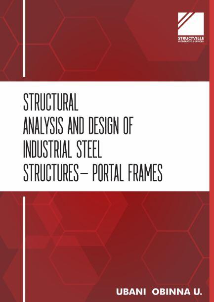
In our commitment to spreading civil engineering knowledge, a simple textbook has been written (part of Structville webinar proceedings) to present a brief but important aspect of portal frame design. The publication contains explanations on different types of portal frames, considerations in the design of portal frames, functional components of portal frames, actions on portal frames, and a design example of portal frames using elastic analysis. The design code adopted in the publication is BS EN 1993-1-1:2005 (Eurocode 3).
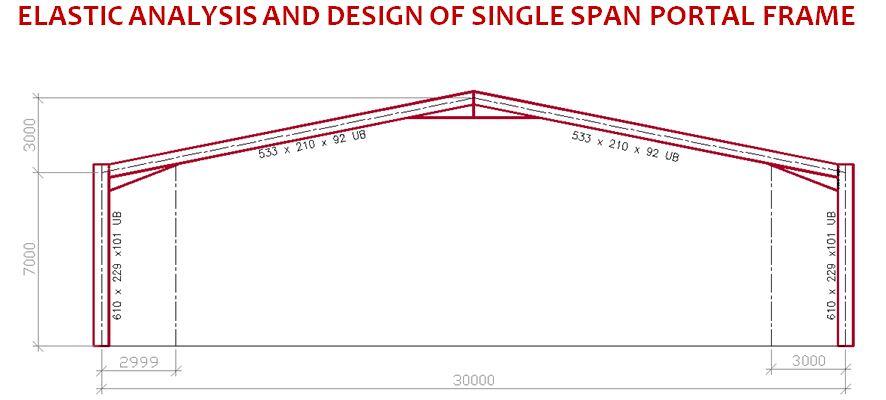
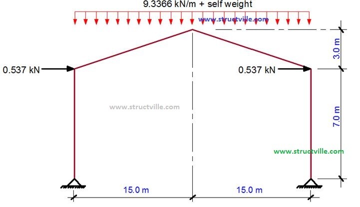
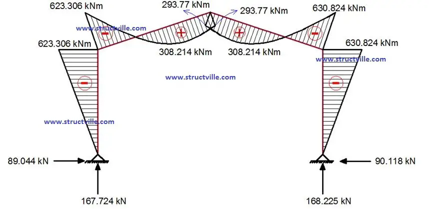
In addition, anyone who purchases the publication (price is ₦2,050) receives a video tutorial on modelling of portal frames in Staad Pro for free.
The cost of the publication is ₦2,050 only. To purchase, click HERE
To purchase the full webinar materials (including videos of discussions and models) for ₦4,100 only, click HERE







Hi , I would like to purchase the book, can it be sent to my country..or in softcopy version?
I have purchased the book over a long time ago
but not with the tutorial video or full webinar then