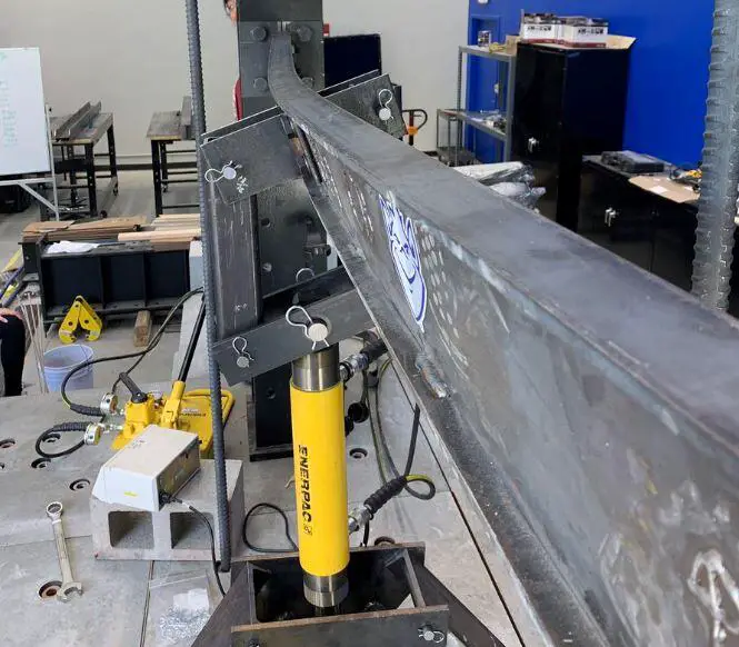
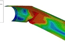
When a laterally unrestrained beam is subjected to bending about the major axis, there is a need to check for lateral-torsional buckling. Lateral-torsional buckling is a type of buckling that involves a combination of lateral deflection of beams and twisting, and typically occurs in open cross-sections.
The phenomenon occurs on the compression flange of the member and depends on factors such as the loading conditions, lateral restraint conditions, and geometry of the compression flange. Steel beams with sufficient lateral restraint to the compression flange may not need to be checked for lateral-torsional buckling. Cross-sections such as circular hollow sections or square box sections are also not susceptible to lateral-torsional buckling.
Lateral restraint to a steel beam in a building may be provided by;
- Concrete floor slab on beams (inclusive of composite metal deck)
- Sheeting or metal decking on roofs (spanning perpendicular to the beam)
- Secondary beams to primary beams
- Purlins on rafters
- Bracings, etc
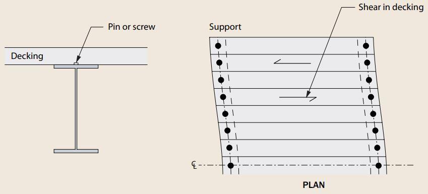
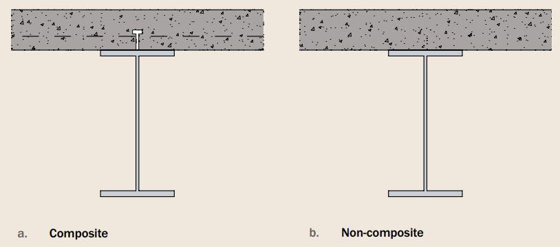
In general, the bracing system assumed to provide effective lateral restraint must be capable of resisting an equivalent stabilising force qd (defined in clause 5.3.3(2) of EC3), the value of which depends on the flexibility of the bracing system.
Design for Lateral-Torsional Buckling
The design bending moment is denoted by MEd (bending moment design effect), and the lateral-torsional buckling resistance by Mb,Rd (design buckling resistance moment). The design requirement is that MEd must be shown to be less than Mb,Rd, and checks should be carried out on all unrestrained segments of beams (between the points where lateral restraint exists).
The design buckling resistance of a laterally unrestrained beam (or segment of beam) should be taken as;
Mb,Rd = χLTWyfy/γm0
where Wy is the section modulus appropriate for the classification of the cross-section, as given below. In determining Wy, no account need to be taken for fastener holes at the beam ends.
Wy = Wpl,y for Class 1 or 2 cross-sections
Wy = Wel,y for Class 3 cross-sections
Wy = Weff,y for Class 4 cross-sections
χLT is the reduction factor for lateral torsional buckling.
Solved Example
A simply supported primary beam is required to span 7m and to support two secondary beams as shown in the figure below. The secondary beams are connected through fin plates to the web of the primary beam, and full lateral restraint may be assumed at these points. Check the suitability of UKB UB 533 x 210 x 92 for the primary beam assuming grade S275 steel.

Let ∑MB = 0;
7VA – (350 × 5.7) – (375 × 1.3) = 0
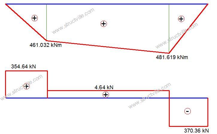
VA = 354.64 kN
Let ∑MA = 0;
7VB – (350 × 1.3) – (375 × 5.7) = 0
VB = 370.36 kN
MB = 354.64 × 1.3 = 461.032 kNm
MC = (354.64 × 5.7) – (350 × 4.4) = 481.619 kNm
UB 533 x 210 x 92
E = 210000 N/mm2
G = 81000 N/mm2
Properties of UB 533 x 210 x 92
h = 533.1 mm
b = 209.3 mm
tw = 10.1 mm
tf = 15.6 mm
r = 12.7 mm
A = 11700 mm2
Iy = 55200 cm4
Iz = 2390 cm4
IT = 7.57 x 106 mm4
IW = 1.6 x 1012 mm6
Wel,y = 2070 cm3
Wel,z = 228 cm3
Wpl,y = 2360 cm3
Wpl,z = 356 cm3
Section Classification
ε = √235/fy = √235/275 = 0.92
Web
cw = d = h – 2tf – 2r = 476.5 mm
cw/tw = 47.18
The limit for class 1 is 72ε = 66.24
cw/tw = 47.18 < 66.24
Therefore the web is class 1 Plastic
Flange
c = [(b – tw – 2r)]/2 = [209.3 – 10.1 – (2 × 12.7)]/2 = 86.9 mm
cf/tf = 5.57
The limit for class 1 is 9ε = 9 × 0.92 = 8.28
5.57 < 8.28
Therefore the flange is Class 1 (plastic)
Therefore the beam section is class 1
Bending Resistance (Clause 6.2.5 BS EN 1993-1-1)
Mpl,y,Rd = (Wplfy)/γm0 = (2360 × 103 × 275)/1.0 × 10-6 = 649 kNm
Maximum moment on the beam My,Ed = 481.619 kNm
481.619 < 649 kNm Ok
Shear Resistance (Clause 6.2.6 EN 1993-1-1)
Shear area Av = A – 2btf + (tw + 2r)tf but not less than ηhwtw
Av = 11700 – (2 × 209.3 × 15.6) + (10.1 + 2 × 12.7) × 15.6 = 5723.64 mm2
ηhwtw = 1.0 × 501.9 × 10.1 = 5069.19 mm2
Therefore take Av = 5723.64 mm2
Vpl,Rd = [Av(fy⁄√3)]/γm0 = [5723.64 (275⁄√3)]/1.0 × 10-3 = 908.749 kN
VEd = 370.36 kN < 908.749 kN Ok
Bending and Shear Interaction (clause 6.2.8 BS EN 1993-1-1)
When shear force and bending moment act simultaneously on a cross-section, the effect of the shear force can be ignored if it is smaller than 50% of the plastic shear resistance.
0.5Vpl,Rd = 0.5 × 908.749 = 454.374 kN
370.36 kN < 454.374 kN, therefore the effect of shear on the moment resistance can be ignored.
Lateral torsional buckling (segment B – C)
Lcr,T = 4.4 m
h/b = 533.1/209.3 = 2.54 > 2.0
Therefore select buckling curve : c = 0.49 (Table 6.5 EC3)
Moment diagram of the point between restraints
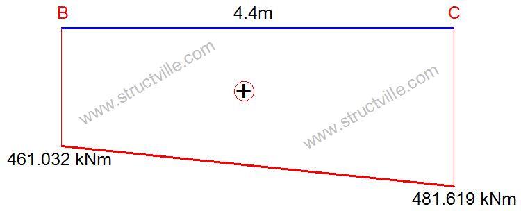
Ratio of end moments ψ = 461.032/481.619 = 0.957
C1 = 1.88 – 1.40ψ + 0.52ψ2 = 1.01 < 2.7 Okay
Mcr = C1 × (π2EIz)/(kL2 ) × [Iw/Iz + (kL2GIT)/(π2EIz )]0.5
Mcr = 1.01 x [(π2 × 210000 × 2390 × 104)/44002] × [(1.6 × 10¹²)/(2390 × 104) + (44002 × 81000 × 75.7 × 104)/(π2 × 210000 × 2390 × 104)]0.5 x 10-6 = 779.182 kNm
Non-dimensional lateral torsional slenderness λLT
λLT = √[(Wpl,yfy)/Mcr ] = √[(2360000 × 275)/(779.182 × 106] = 0.912
λLT,0 = 0.4, and β = 0.75
ϕLT = 0.5[1+ αLT (λLT – λLT,0) + βλLT2]
ϕLT = 0.5[1 + 0.49(0.912 – 0.4) + 0.75 × 0.9122] = 0.937
χLT = 1/[ϕLT + √(ϕLT2 – βλLT2)] but χ ≤ 1.0
χLT = 1/([0.937 + √(0.9372 – 0.75 × 0.9122)] = 0.6938
Mb,Rd = χLTWyfy/γm0 = (0.6938 × 2360 × 103 × 275)/1.0 × 10-6 = 450.33 kNm
MEd/Mb,Rd = 481.619/450.33 = 1.06 > 1.0
Therefore the section is not okay to resist lateral torsional buckling on the primary beam.
References
Gardner L. (2011): Stability of Steel Beams and Columns (In Accordance with the Eurocodes and UK National Annex). SCI – Steel Construction Institute, Berkshire UK.







By provividing stiffeners at a spacing of 1.2 to 1.5 to to Beam on both sides will improve very much Torsional Resistence of Beam. This can be proved by Ansys.