In the design of portal frames and other steel structures, moment-resisting bases can be provided if large lateral forces and bending moments are anticipated. This can lead to the economical design of the frame members, but the base will have to be carefully designed as a moment-resisting connection. Therefore such bases are expected to transfer bending moment and axial forces between the steel members and the concrete substructure. Depending on the direction of the moment and the magnitude, base plates can be symmetric or asymmetric.
For the design of moment-resisting base plates, the smallest diameter of bolts to be considered should be M20, even though M30 bolts are deemed the most appropriate. Larger bolts in smaller numbers are usually preferable. All holding-down bolts should be provided with an embedded anchor plate for the head of the bolt to bear against.
The sizes of anchor plates are chosen so as not to apply stress of more than 30 N/mm2 at the concrete interface, assuming 50% of the plate is embedded in concrete. When the moments and forces are high, the holding-down system may need to be designed in conjunction with the reinforcement in the base.
Design Methodology
The design methodology for a moment-resisting base plate connection involves using an iterative approach/experience to select the best base dimensions and bolt configuration. This arrangement is then evaluated for its resistance against the anticipated actions from the superstructure.
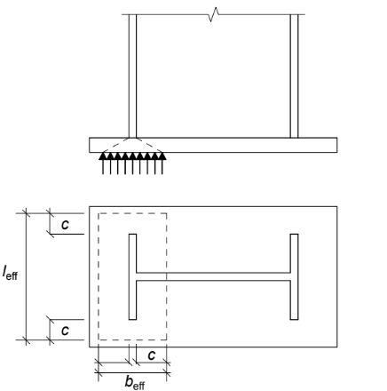
In EN 1993-1-1:2005, the resistance of a base plate subjected to bending moment and axial force is assumed to be provided by two T-stubs, one in tension, and the other in compression. The resistance of the stub in tension is assumed to be provided by the holding down bolts, while the resistance of the stub in compression is assumed to be provided by a compression zone in the concrete, which is concentric with the column flange as shown below.
The design verification of a moment-resisting base plate, therefore, involves the following steps;
STEP 1
Evaluate the design forces in the equivalent T-stubs for both flanges. For a flange in compression, the force may be assumed to be concentric with the flange. For a flange in tension, the force is assumed to be along the line of the holding down bolts.
STEP 2
Evaluate the resistance of the equivalent T-stub in compression.
STEP 3
Evaluate the resistance of the equivalent T-stub in tension
STEP 4
Verify the adequacy of the shear resistance of the connection.
STEP 5
Verify the adequacy of the welds in the connection.
STEP 6
Verify the anchorage of the holding down bolts.
Design Example
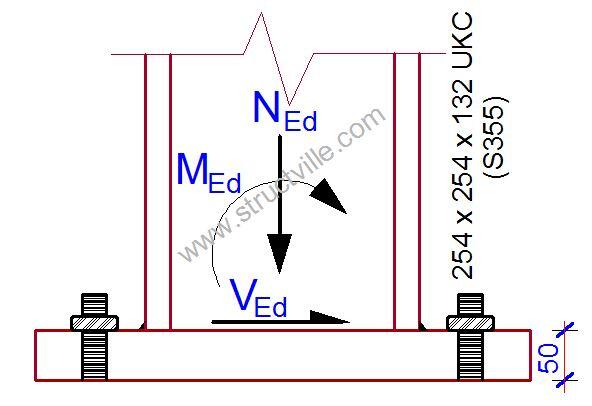
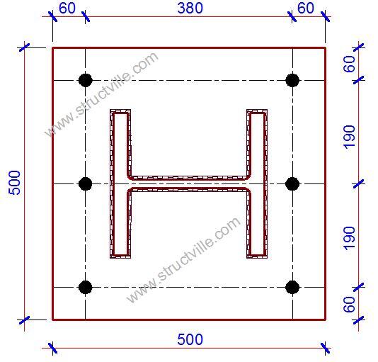
Verify the capacity of the base plate arrangement in grade S275 steel shown below to resist the following actions;
MEd = 125 kNm
NEd = -870 kN (compression)
VEd = 100 kN
Column
From data tables for 254 x 254 x 132 UKC in S355
Depth hc = 276.3 mm
Width bc = 261.3 mm
Flange thickness tf,c = 25.3 mm
Web thickness tw,c = 15.3 mm
Root radius rc = 12.7 mm
Elastic modulus (y-y axis) Wel,y,c = 1630000 mm3
Plastic modulus (y-y axis) Wpl,y,c = 1870000 mm3
Area of cross section Ac = 16800 mm2
Depth between flanges hw,c = hc – 2 tf,c = 276.3 – (2 x 25.3) = 200.4 mm
Base plate
Steel grade S275
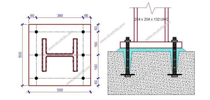
Depth hbp = 500 mm
Gross width bg,bp = 500 mm
Thickness tbp = 50 mm
Concrete
The concrete grade used for the base is C30/37
Bolts
M24 8.8 bolts
Diameter of bolt shank d = 24 mm
Diameter of hole d0 = 26 mm
Shear area (per bolt) As = 353 mm2
Number of bolts on either side n = 3
MATERIAL STRENGTHS
Column and base plate
The National Annex to BS EN 1993-1-1 refers to BS EN 10025-2 for values of nominal yield and ultimate strength. When ranges are given the lowest value should be adopted.
For S355 steel and 16 < tf,c < 40 mm
Column yield strength fy,c = ReH = 345 N/mm2
Column ultimate strength fu,c = Rm = 470 N/mm2
For S275 steel and tbp > 40 mm
Base plate yield strength fy,bp = ReH = 255 N/mm2
Base plate ultimate strength fu,bp = Rm = 410 N/mm2
Concrete
For concrete grade C30/37
Characteristic cylinder strength fck = 30 MPa = 30 N/mm2
The design compressive strength of the concrete is determined from:
fcd = αccfck/γc
fcd = (0.85 x 30)/1.5 = 17 N/mm2
For typical proportions of foundations, conservatively assume:
fjd = fcd = 17 N/mm2
Bolts
For 8.8 bolts
Nominal yield strength fyb = 640 N/mm2
Nominal ultimate strength fub = 800 N/mm2
PARTIAL FACTORS FOR RESISTANCE
Structural steel
γM0 = 1.0
γM1 = 1.0
γM2 = 1.1
Parts in connections
γM2 = 1.25 (bolts, welds, plates in bearing)
DISTRIBUTION OF FORCES AT THE COLUMN BASE
The design moment resistance of the base plate depends on the resistances of two T-stubs, one for each flange of the column. Whether each T-stub is in tension or compression depends on the magnitudes of the axial force and bending moment. The design forces for each situation are therefore determined first.
Forces in column flanges
Forces at flange centroids, due to moment:
NL,f = MEd/(h – tf) = [125/(276.3 – 25.3)] x 103 = 498 kN (tension)
NR,f = -MEd/(h – tf) = -[125/(276.3 – 25.3)] x 103 = -498 kN (compression)
Forces due to axial force:
NL,f = NR,f = NEd/2 = -870/2 = -435 kN
Total force:
NL,f = 498 – 435 = 63 kN (tension)
NR,f = – 498 – 435 = -933 kN (compression)
In this case, the left side is in tension and the right side is in compression. The resistances of the two T-stubs will, therefore, be centred along the lines shown below:
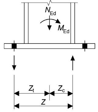
Forces in T-stubs of the base plate
Assuming that tension is resisted on the line of the bolts and that compression is resisted concentrically under the flange in compression, the lever arms from the column centre can be calculated as follows:
zt = 380/2 = 190 mm
zc = (276.3 – 25.3)/2 = 125.5 mm
In this design situation, the left flange is in tension and the right in compression.
Therefore, zL = zt and zR = zc
NLT = [MEd/(zL + zR)] + [(NEd x zR)/(zL + zR)] = [125/(190 + 125.5)] x 103 + [-(870 x 125.5)/(190 + 125.5)] = 50.127 kN
NRT = -[MEd/(zL + zR)] + [(NEd x zL)/(zL + zR)] = -[125/(190 + 125.5)] x 103 + [-(870 x 125.5)/(190 + 125.5)] = -742.265 kN
RESISTANCE OF EQUIVALENT T-STUBS
Resistance of compression T-stub
The resistance of a T-stub in compression is the lesser of:
- The resistance of concrete in compression under the flange (Fc,pl,Rd)
- The resistance of the column flange and web in compression (Fc,fc,Rd)
Compressive resistance of concrete below the column flange. The effective bearing area of the joint depends on the additional bearing width, as shown below.
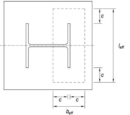
Determine the available additional bearing width (c), which depends on the plate thickness, plate strength and joint strength.
c = tbp x [√fybp/(3fjdγM0)] = 50 x [√255/(3 x 17 x 1.0)] = 112 mm
Thus the dimensions of the bearing area are,
beff = 2c + tfc = (2 x 112) + 25.3 = 249.3 mm
leff = 2c + bc = (2 x 112) + 261.3 = 485.3 mm
The area of bearing is,
Aeff = 249.3 x 485.3= 120985 mm2
Thus, the compression resistance of the foundation is,
Fc,pl,Rd = Aefffjd
Fc,pl,Rd = 120985 x 17 x 10-3 = 2057 kN, > NR,T = 742.265 kN (maximum value).
This is therefore satisfactory
Resistance of the column flange and web in compression
The resistance of the column flange and web in compression is determined from:
Fc,fcRd = Mc,Rd/(hc – tfc)
Mc,Rd is the design bending resistance of the column cross-section = 645 kNm (see page 402 of P363)
If VEd > Vc,Rd/2, the effect of shear should be allowed for
Vc,Rd = 705 kN (see page 234 of P363)
VEd = 100 kN
By inspection:
VEd < Vc,Rd/2
Therefore, the effects of shear may be neglected and hence
Mc,Rd = 645 kNm
Fc,fcRd = [(645 x 106)/(276.3 – 25.3)] x 10-3 = 2569.4 kN
As, Fc,pl,Rd < Fc,fc,Rd the compression resistance of the right hand T-stub is:
Fc,pl,Rd = 2057 kN
Fc,pl,Rd> NR,T = 742.265 kN Satisfactory
RESISTANCE OF TENSION T-STUB
The resistance of the T-stub in tension is the lesser of:
- The base plate in bending under the left column flange, and
- The column flange/web in tension
Resistance of base plate in bending
The design resistance of the tension T-stub is given by:
Ft,pl,Rd = Ft,Rd = min{FT,1-2,Rd; FT,3,Rd}
Where FT,1-2,Rd is the ‘Mode 1 / Mode 2’ resistance in the absence of prying and FT,3,Rd is the Mode 3 resistance (bolt failure).
FT,1-2,Rd = 2MPl,1,Rd/m
MPl,1,Rd = (0.25∑leff,1tbp2fybp)/γM0
∑leff,1 = is the effective length of the T-stub, which is determined from the equations below;
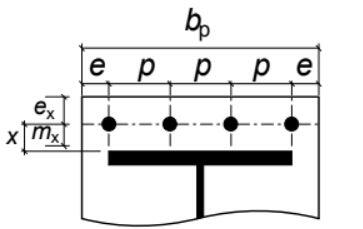
bp = 500 mm
p = 190 mm
e = 60 mm
ex = 60 mm
mx = 52 mm
n = 3 (number of rows of bolt)
Non-circular patterns
- Single curvature; leff,nc = bp/2 = 500/2 = 250 mm
- Individual end yielding; leff,nc = 0.2n(4mx + 1.25ex) = 1.5(4 x 52 + 1.25 x 60) = 424.5 mm
- Corner yielding of outer bolts, individual yielding between; leff = 2mx + 0.625ex + e + (n – 2)(2mx + 0.625ex) = 2(52) + 0.625(60) + 60 + 1 x (2 x 52 + 0.625 x 60) = 324.25 mm
- Group end yielding; leff = 2mx + 0.625ex + 0.5(n – 1)p = 2(52) + 0.625(60) + (0.5 x 2 x 190) = 331.5 mm
Circular patterns
- Individual circular yielding; leff,cp = nπmx = 3 x π x 52 = 490 mm
- Individual end yielding; leff,cp = 0.5n(πmx + 2e) = 1.5(π x 52 + 2 x 60) = 425 mm
The minimum is leff,1 = 250 mm
MPl,1,Rd = (0.25∑leff,1tbp2fybp)/γM0 = [(0.25 x 250 x 502 x 255)/1.0] x 10-6 = 39.84 kNm
FT,1-2,Rd = 2MPl,1,Rd/m = (2 x 39.84)/0.052 = 1532.3 kN
Ft,3,Rd = ∑Ft,Rd
For class 8.8. M24 bolts; Ft,Rd = 203 kN
Ft,3,Rd = 3 x 203 = 609 kN
Ft,pl,Rd = Ft,Rd = min{FT,1-2,Rd; FT,3,Rd} = min{1532.3; 609} = 609 kN
NLT = 50.127 kN < Ft,pl,Rd = 609 kN Okay.
WELD DESIGN
Welds to the tension flange
The maximum tensile design force is significantly less than the resistance of the flange, so a full-strength weld is not required. The design force for the weld may be taken as that determined between column and base plate in STEP 1, i.e. 498 kN (NL,f)
For a fillet weld with s = 12 mm, a = 8.4 mm
The design resistance due to transverse force is:
Fnw,Rd = (Kafu/√3)/βwγM2
where K = 1.225, fu = 410 N/mm2 and βw = 0.85 (using the properties of the material with the lower strength grade – the base plate)
Fnw,Rd = [(1.225 x 8.4 x 410) / √3]/(0.85 x 1.25) = 2.29 kN/mm
Length of weld, assuming a fillet weld all around the flange:
For simplicity, two weld runs will be assumed, along each face of the column flange. Conservatively, the thickness of the web will be deducted from the weld inside the flange. An allowance equal to the leg length will be deducted from each end of each weld run.
L = (261.3 – 2 x 12) + (261.3 – 12 – 4 x 12) = 438.6 mm
Ft,weld,Rd = 2.29 x 438.6 = 1004 kN, > 498 kN – Satisfactory
Welds to the compression flange
With a sawn end to the column, the compression force may be assumed to be transferred in bearing. There is no design situation with moment in the opposite direction, so there should be no tension in the right-hand flange. Only a nominal weld is required. Commonly, both flanges would have the same size weld.
Welds to the web
Although the web weld could be smaller and sufficient to resist the design shear, it would generally be convenient to continue the flange welds around the entire perimeter of the column.








Hanger balding
Good work Eng.
i have learnt of your elaborate work of recent and excellent simplification
For N(LT) where din the Moment of 350kn.m from?
Good job
thank you Eng.
Where did you considered the k=1.225 value for design resistance in transverse direction in weld design