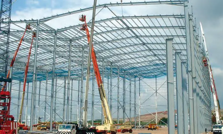
Steel portal frames provide economical solution for construction of industrial structures, warehouses, churches or other buildings with large enclosures. The loading scheme on portal frames usually includes dead load, wind load, imposed load, service loads, snow loads, imperfections, thermal loads, crane loads etc.
In the plastic analysis of portal frames, preliminary analysis is usually carried out to determine member sizes before detailed checks are carried out to determine the adequacy of the selected sections. Weller’s chart is usually used to quickly determine the plastic moments that can enable initial sizing of members. The simplicity of the charts depends on a series of three charts developed by Weller. The application of the method relies on the following assumptions;
(1) The rafter depth is approximately span / 55
(2) The hunch length is approximately span /10
(3) The rafter slope lies between 10° and 20°.
(4) The ratio of span to eaves height is between 2 and 5.
(5) The hinges in the mechanism are formed at the level of the underside of the haunch in the column and close to the apex.
Each chart requires a knowledge of the geometry of the frame and the design loading as input data in order to determine approximate sizes for the column and rafter member.
Application Example
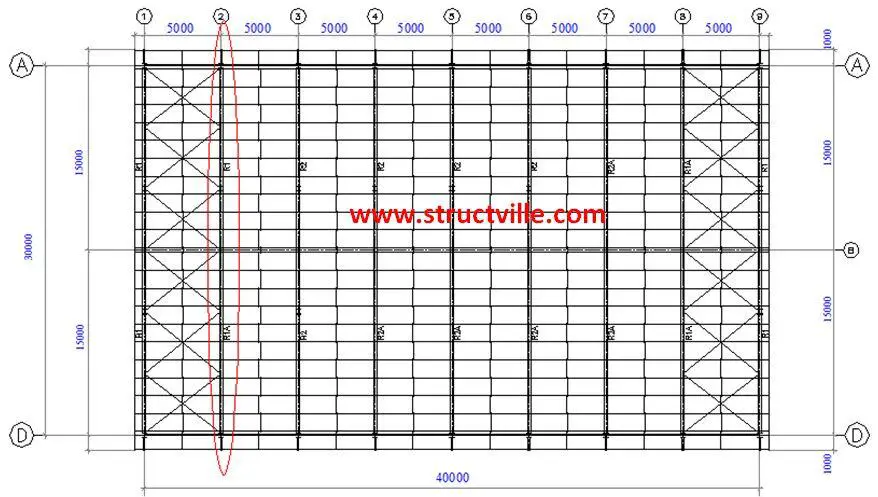 |
| Fig 1: General Arrangement of Steel Structure |
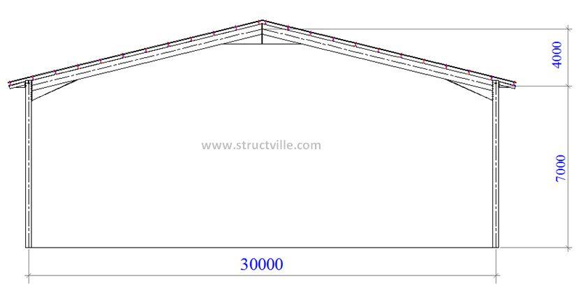 |
| Fig 2: Portal Frame |
Length of building = 40 m
Width of building = 30 m
Height to eaves = 7.0 m
Height to roof top = 11.0 m
Consider the portal frame on gridline 2. The gravity load on the portal frame is analysed as follows;
Load Analysis
(1) Dead Load
Aluminium roof sheeting = 0.04 kN/m2
Insulation (assume gypsum boards per 10 mm thickness) = 0.077 kN/m2
Other permanent services = 0.15 kN/m2
Steel purlins (take) = 0.03 kN/m2
Self weight of rafter (take) = 0.15 kN/m2
Total = 0.447 kN/m2 on slope
Angle of inclination of roof = 15°
Load on plan = 0.447/cos 15° = 0.4627 kN/m2
Spacing of portal frame = 5 m centre to centre
Therefore dead load on roof gk = 0.4627 kN/m2 x 5m = 2.31 kN/m
(2) Imposed Load
According to BS 6399 Part 3, for roof with slope less than 30°, a minimum imposed load of 0.6 kN/m2 on plan should be provided as long as no access except for cleaning and maintenance is provided.
For this design, let us adopt an imposed load of 0.75 kN/m2
qk = 0.75 kN/m2
Imposed load on roof = 0.75 x 5m = 3.75 kN/m
At ultimate limit state;
p = 1.4gk + 1.6qk = 1.4(2.31) + 1.6(3.75) = 9.234 kN/m
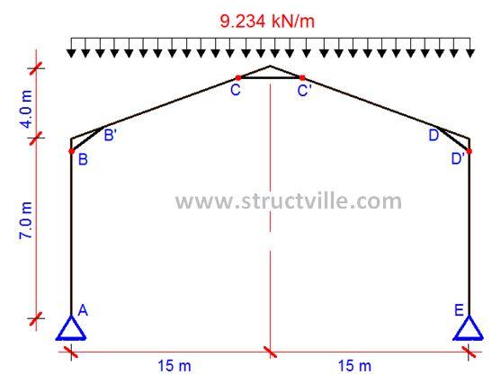 |
| Fig 3: Portal Frame with ULS Gravity Load |
Step by Step Analysis
(a) Calculate the span/height to eaves ratio = L/h
Span/height to eaves ratio L/h = 30/7 = 4.285
(b) Calculate the rise/span ratio = r/L
Height of Rise / span ratio r/L = 4/30 = 0.133
(c) Calculate the total design load FL on the frame and then calculate FL2, where F is the load per unit length on plan of span L
Ultimate gravity load = 9.234 kN/m (see Fig. 3)
Total load on the frame (wL) = 9.234 x 30 = 277.02 kN
Parameter wL2 = 9.234 x 302 = 8310.6 kNm
(d) From Fig 4 (Chart 1) obtain the horizontal force ratio HFR at the base from r/L and L/h
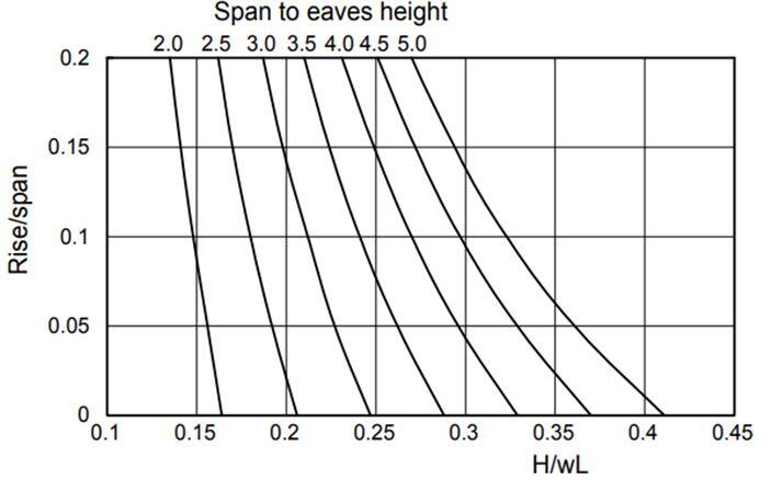 |
| Fig 4: Chart 1 |
H/wL = 0.27
Hence, horizontal force ratio HFR = 0.27
(e) Calculate the horizontal force at the base of span H = HFR wL
Hence, H = 0.27 x 277.02 = 74.795 kN
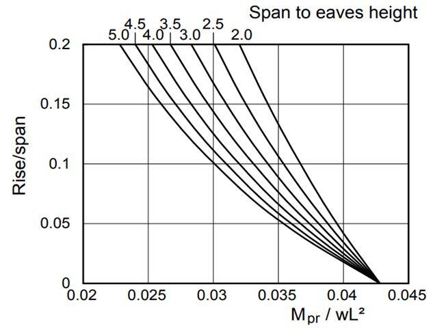
(f) From Fig 5 (Chart 2), obtain the rafter Mp ratio MpR from r/L and L/h.
 |
| Fig 5: Chart 2 |
Rafter MpR/wL2 ratio = 0.028
(g) Calculate the Mp required in the rafter from Mp(rafter) = MpR x wL2
Mp,Rafter = 0.028 x 8310.6 = 232.696 kNm
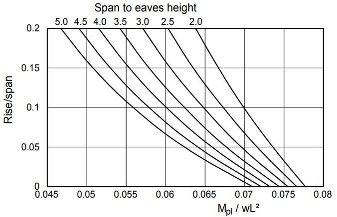
(h) From Fig 6 (Chart 3), obtain the column Mp ratio from r/L and r/h
 |
| Fig 6: Chart 3 |
Column MpC/wL2 ratio = 0.057
(i) Calculate the Mp required in the column from Mp,Column = MpC x wL2
Mp,Column = 0.057 x 8310.6 = 473.70 KNm
(j) Determine the plastic moduli for the rafter Wpl,y,R and the column Wpl,y,C from
Wpl,y,R = Mp,Rafter /fy
Wpl,y,C = Mp,Column/fy
Where fy is the yield strength = 275 Mpa.
Using the plastic moduli, the rafter and column sections may be chosen from the range of plastic sections as so defined in the section books
(a) For Rafters
Plastic Moment Mp,Rafter = 232.696 kNm
Plastic Modulus Required Sx
Sx = (232.696 x 10³) / 275 = 846 cm3
Try UB 356 x 171 x 57 kg/m (Plastic modulus = 1010 cm3)
(b) For Columns
Plastic Moment Mp,Columns = 473.7 kNm
Plastic Modulus Required
Sx = (473.7 x 10³) / 275 = 1722 cm3
Try UB 457 x 191 x 82 kg/m (Plastic modulus = 1830 cm3)
These trial sections are usually checked for the following in the detailed design;
(a) In-plane stability
(b) Column Stability
(c) Rafter Stability
(d) Haunch Stability
(e) Deflection etc.
Thank you for visiting Structville today and God bless you.





Thanks
Nice one, thanks Ubani. I usually consider roof load, was it deliberately ommited in your load estimates?