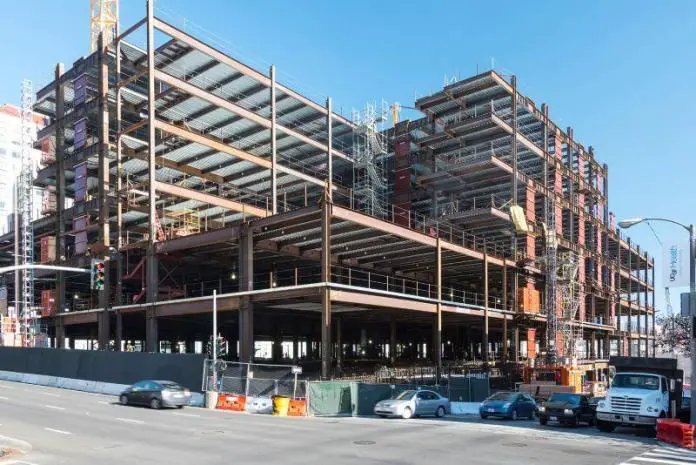
When the beam-to-column connections in a frame are sufficiently rigid to maintain the original angles between intersecting members, the frame is considered a moment-resisting (rigid) frame. In essence, moment-resisting frames comprise the beams, columns, and the rigid connection between them.
The stiffness of the beams and columns are relied upon for resisting gravity and lateral loads and are essentially designed for such. Moment-resisting frames can be made of steel or reinforced concrete.
The rigid frame action is the development of shear forces and bending moments in the frame members and joints to resist lateral loads. By reducing positive moments in beam spans, the continuity at both ends of beams also helps moment-resisting frames in resisting gravity loads more effectively.
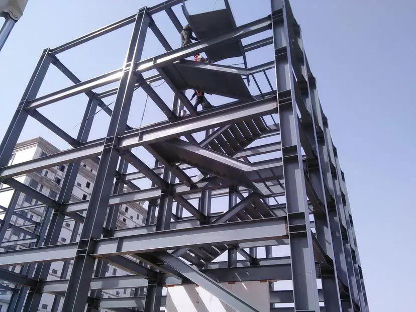
The versatility of moment-resisting frames in architectural planning gives them certain advantages in building applications. They can be positioned at the building’s façade without having their depths restricted in any way. However, some restrictions on beam depths must be observed to allow for the passage of mechanical and air conditioning ducts.
They may also be positioned throughout the interior of the structure. They are regarded as having greater architectural versatility than other systems like braced frames or shear walls because there are no bracing elements to obstruct open spaces or openings.

In order to prevent storey drift under lateral loads, the depths of frame members are frequently governed by stiffness rather than strength. The lateral displacement of one level in relation to the level below is referred to as the story drift. It is a major concern in the serviceability assessment of buildings especially because of the effects of wind.
Commonly used drift limitations for wind-related building designs range from 1/400 to 1/500 of the story height. These restrictions are thought to be generally adequate to reduce damage to nonstructural walls and partitions, cladding, and other surfaces.
Then inherent flexibility of moment-resisting frames could lead to more drift-induced nonstructural damage than in other systems under seismic loads. It is important to keep in mind that seismic drift, which includes structures’ inelastic responses, is normally limited to 1/50 of the story height, which is around ten times bigger than the permitted wind drift. Particularly for frames intended to withstand seismic loads, the strength and ductility of the connections between beams and columns are very important factors to consider.
Consider the welded moment connection details from Figure 3, which were applied in North American seismic zones during the 25 years before the Northridge earthquake. A high-strength bolted shear tab connection and full-penetration field-welded top and bottom beam flanges were generally used for the connection. This kind of connection was thought to be capable of producing significant inelastic rotations.
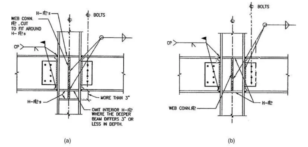
The January 17, 1994, Northridge earthquake in California, with a Richter magnitude of 6.7, and the January 18, 1995 Kobe earthquake, with a Richter magnitude of 6.8, both damaged over 200 steel moment-resisting frame buildings and made engineers less confident in the use of the moment frame for seismic design.
Steel moment frames did not perform as well as planned in either of these earthquakes. The connections that failed almost always belonged to the category depicted in Figure 3. Most of the damage was caused by fractures in the bottom flange weld connecting the girder and column flanges. Additionally, top flange fractures happened often (Bungale, 2005).
New connection procedures have been created, and the majority of construction codes are being amended, in light of the brittle fracture that was seen at the intersections of the beam and column. Designing beams so that the plastic hinges form away from the column face is the typical approach to some new design concepts.
Deflection Behaviour of Moment-Resisting Frames
A moment-resisting frame cannot displace laterally without bending the beams and columns because of the rigid connections between the beams and columns. Therefore, the bending rigidity of the frame elements serves as the main source of lateral stiffness for the entire structure.
It is beneficial to consider the deflections of a rigid frame as composed of two components (comparable to the deflection components of a structural element like a vertical cantilever column) to comprehend its lateral deflection characteristics.
The cantilever column’s primary deflection is caused by bending, and its secondary component is caused by shear. The shear component might not be taken into account when calculating deflection unless the column is reasonably short. However, both of these elements carry equal importance in moment-resisting frames. Cantilever bending and frame racking are common names for the bending and shear deflection parts of rigid frames.
Cantilever Bending Component
A moment-resisting frame behaves like a vertical cantilever when resisting overturning moments, which causes axial deformation of the columns. The columns on the windward face lengthen while those on the leeward face shorten. The building rotates about a horizontal axis due to this alteration in column lengths. The resulting lateral deflection, as depicted in Figure 5, is comparable to the cantilever’s bending deflection component.

Shear Racking Component
This rigid frame response, depicted in Figure 6, is comparable to the cantilever column’s shear deflection component. Due to the rigid connections between the beams and columns, bending moments and shears develop in the beams and columns as the frame moves laterally. The horizontal shear above a given level due to lateral loads is resisted by shear in each of the columns of that story (Figure 6).

The storey columns then begin to bend in a double curvature with points of contraflexure at roughly midstory levels as a result of this shear. Equilibrium is achieved when the sum of the moments of the columns above and below a joint equals the sum of the moments of the beams on each side of the column.
The beams also bend in a two-fold curvature to resist the bending, with points of contraflexure roughly in the middle of the span. The overall shear racking of the frame is caused by the accumulated bending of the columns and beams. According to Fig. 3.4b, the deflected shape caused by this component has a shear deflection structure.
About 70% of a moment frame’s overall sway results from the shear mode of deformation, with the remaining 30% coming from column bending and the other 10% to 15% from beam flexure. This is due to the fact that in a rigid frame, the column stiffness, as determined by the Ic/Lc ratio, is often significantly higher than the beam stiffness ratio, Ib/Lb, where;
Ib = moment of inertia of the beam
Ic = moment of inertia of column
Lb = length of the beam
Lc = length of the column
Therefore, to reduce lateral deflection, one should consider starting with increasing the stiffness of the beams. However, it is advisable to investigate the relative beam and column stiffnesses before making adjustments to the member stiffnesses in nontypical frames, such as for those in framed tubes with column spacing that is close to floor-to-floor height (Bungale, 2005).
The story drift increases with height due to the cumulative effect of building rotation, but that caused by shear racking tends to remain constant with height. In the highest stories, cantilever bending contributes more to story drift than shear racking does. Except in very tall and slender rigid frames, the bending impact typically does not exceed 10 to 20% of that caused by shear racking.
As a result, a medium-rise frame’s overall deflected shape typically has a shear deflection arrangement (Bungale, 2005). Therefore, it is possible to consider the total lateral deflection of a rigid frame as a combination of the following elements:
• Cantilever deflection due to axial deformation of columns (15 to 20%).
• Frame shear racking due to bending of beams (50 to 60%).
• Frame racking due to bending of columns (15 to 20%).
The panel zone of a beam-column connection, which is defined as the rectangular segment of the column web within the column flanges and beam continuity plates, along with the previously mentioned variables, also contributes to the overall lateral deflection of the frame. However, its impact rarely goes above 5% of the total deflection.
References
Bungale S. T. (2005): Wind and earthquake resistant buildings structural analysis and design. Marcel Dekker, New York

