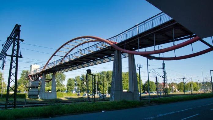
A footbridge (also called a pedestrian bridge) is a structure that is designed to enable pedestrians to cross over natural or man-made obstacles such as busy highways, railways, water bodies, gullies, etc, with minimal risk. Pedestrians are generally humans that are travelling on foot and also includes people in a wheelchair, or people that are pushing tramps. In the design of a footbridge, it is very important to evaluate the loads (actions) that it will encounter during its service life.
The possible loads that footbridges are subjected to are;
- Human traffic
- Self-weight of the bridge and its ancillaries
- Wind load
- Earthquake load (where applicable)
- Snow load (where applicable)
- Dynamic water pressure (for bridges crossing water bodies)
- Thermal actions
- Possible accidental action from impact
In the recent wake of the need for sustainable urban transportation, some pedestrian bridges are being designed to accommodate both pedestrians and cyclists. Furthermore, to ensure that footbridges are accessible to the disabled and mobility-impaired people, there should be provision for ramps or lifts so that they can cross over safely. The use of lifts should be a better option compared to ramps due to the high demand for space, especially in urban areas.
Pedestrian bridges can also serve as monumental structures that can be used for the decoration and beautification of cities and streets. Beautiful and well designed footbridges can adorn the skylines of a city, and form unique features that can easily attract tourists.

Actions on Footbridges
The actions on pedestrian bridges can be found in section 5 of EN 1991-2 (Eurocode 1 Part 2). The section covers explicitly actions on footways, cycle tracks, and footbridges. It is important to note that the uniformly distributed load qfk and the concentrated load Qfwk given in section 5 of EN 1991-2, where relevant can be also used for parts of road and railway bridges accessible to pedestrians. However, all other variable actions described therein apply to footbridges only.
Furthermore, it is important to note that the load models and their representative values take into account dynamic amplification effects, and can be used for all kind of serviceability and ultimate limit state static calculations, except fatigue limit states. The load models do not cover the effects of loads on construction sites and should be separately specified, where relevant.
The imposed loads defined in EN 1991-2 result from pedestrian and cycle traffic, minor common construction and maintenance loads (e.g. service vehicles), and accidental situations. These loads give rise to vertical and horizontal, static, and dynamic forces.
Static Models for Vertical Loads on Footbridges
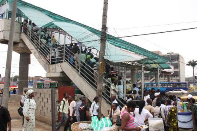
Three mutually exclusive vertical load models can be envisaged for footbridges. They are;
- a uniformly distributed load representing the static effects of a dense crowd;
- one concentrated load, representing the effect of a maintenance load;
- one or more, mutually exclusive, standard vehicles, to be taken into account when maintenance or emergency vehicles are expected to cross the footbridge itself.
The characteristic values of these load models should be used for both persistent and transient design situations.
Uniformly Distributed Loads on Footbridges
The crowd effect on the bridge is represented by a uniformly distributed load. When the risk of dense crowd exists or when specified for a particular project, Load Model 4 for road bridges should be considered also for footbridges. On the contrary, where the application of the aforesaid Load Model 4 is not required, a uniformly distributed load, to be applied to the unfavourable parts of the influence surface longitudinally and transversally, qfk should be defined in the National Annex.
The recommended value, depending on the loaded length L [m] is:
2.5 kN/m2 ≤ qfk = 2 + 120/(L + 30) ≤ 5.0 kN/m2 —— (1)
For road bridges supporting footways or cycle tracks, only the characteristic values (5 kN/m2) or the combination value (2.5 kN/m2) should be considered.
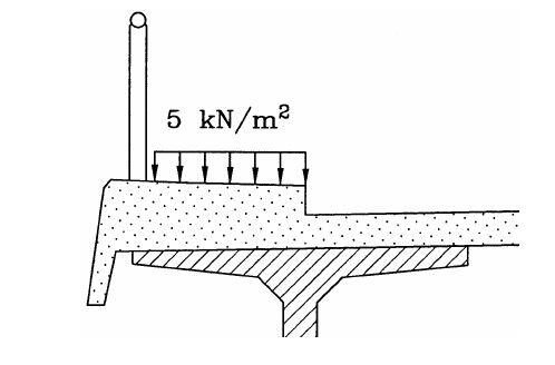
The minimum and maximum crowd load to be applied on bridges irrespective of the span length is therefore 2.5 kN/m2 and 5 kN/m2 respectively. To check the effect of span length on the value of the crowd load, equation (1) can be used. For instance, the crowd load on a pedestrian bridge of length 30 m is given by;
qfk = 2 + 120/(L + 30) = 2 + 120/(30 + 30) = 4 kN/m2
Concentrated load on Footbridges
For local effect assessment, a 10 kN concentrated load Qfwk, representing a maintenance load, should be considered on the bridge, acting on a square surface of sides 10 cm. When the service vehicle (see paragraph below) is taken into account, Qfwk should be disregarded. The concentrated load Qfwk should not be combined with any other variable non-traffic load.
Service/Accidental vehicle on Footbridges
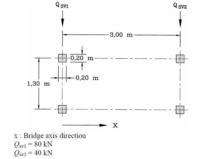
When service vehicles for maintenance, emergencies (e.g. ambulance, fire), or other services must be considered, they should be assigned for the particular project. If no information is available and if no permanent obstacle prevents a vehicle from being driven onto the bridge deck, the special vehicle defined in the figure below should be considered. If consideration of the service vehicle is not requested, the vehicle shown in the figure below should be considered as accidental.
Horizontal forces – characteristic values
A horizontal force Qflk acting along the bridge deck axis at the pavement level should be taken into account for footbridges only, whose characteristic value is equal to the greater of these two values:
– 10 per cent of the total load corresponding to the uniformly distributed load or
– 60 per cent of the total weight of the service vehicle, when relevant.
This horizontal force, which is normally sufficient to ensure the horizontal longitudinal stability of the footbridge, is assumed to act simultaneously with the corresponding vertical load, and in no case with the concentrated load Qfwk.
Groups of traffic loads on footbridges
Vertical loads and horizontal forces due to traffic should be combined, when relevant, taking into account the groups of loads defined in the table below (Table 5.1, EN 1991-2). Each of these groups of loads, which are mutually exclusive, should be considered as defining a characteristic action for combination with non – traffic loads.

As a rule, except for roofed bridges, where appropriate rules are defined in EN 1991-1-3, traffic loads on footbridges are considered not to act simultaneously with significant wind or snow. Wind and thermal actions should not be taken into account as simultaneous. When a combination of traffic loads together with actions specified in other Parts of EN 1991 must be considered, any group of loads in Table 5.1 of EN 1991-2 should be considered as one action.
Application of the load models
The traffic models described above with the exception of the service vehicle model, may also be used for pedestrian and cycle traffic on the areas of the deck of road bridges limited by parapets and not included in the carriageway, or on the footpaths of railway bridges. These actions are free, so that the models of vertical loads should be applied anywhere within the relevant areas in such a way that the most adverse effect is obtained.

