According to section 5 of EN 1991-1-7:2006 (Eurocode 1 Part 7), explosions shall be taken into account in the design of buildings or civil engineering structures where gas is burned or regulated. This requirement also extends to buildings where materials such as explosive gases, or liquids forming explosive vapour or gas are stored or transported (e.g. chemical facilities, vessels, bunkers, sewage constructions, dwellings with gas installations, energy ducts, road and rail tunnels).
Explosion pressures on structural members should be determined taking into account, as appropriate, reactions transmitted to the structural members by non-structural members. The basic principle for design is that the structure shall be designed to resist progressive collapse resulting from an internal explosion, in accordance with EN 1990, 2.1 (4)P. In the design, the failure of some parts of the building may be permitted, but not the key structural members such as columns, slabs, beams, shear walls, etc.
Internal Gas Explosion in a Building
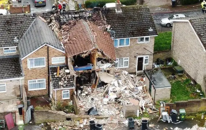
A gas explosion can be defined as a process where the combustion of a premixed gas-air cloud causes a rapid increase of pressure. For the proper functioning of a building, gas is required to supply energy for heating, cooking, and electricity generation. This implies the potential for an accidental explosion. For a gas explosion to occur in a building, the following succession of circumstances is required;
- A gas leakage or release occurs as a result of technical defects in gas installations (pipes, boilers, etc.), human errors during installation, repair, or maintenance of such installations, or in consequence of intentional manipulation.
- The released gas forms, with the oxygen present in the air, an inflammable gas-air cloud in compliance with certain physical requirements.
- A delayed ignition of the gas-air mixture through an ignition source (spark, hot surface, etc) occurs. If the ignition takes place immediately after the gas release, i.e. before an inflammable gas-oxygen cloud is being formed, a fire might occur, but the mixture will not explode.
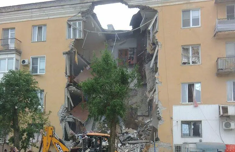
The pressure build-up during a gas explosion in the inside of a building is a consequence of combustion in a confined environment. The combustion process results in increased temperatures due to the transformation of chemically bound energy into heat. Thereby, the expansion of the combustion products, such as CO2 and vapour, will be limited due to confinement by the building closings such as walls and floors, which will cause the pressure to increase [1].
In a completely confined compartment, such as pipes or closed vessels in industrial installations, the maximum pressure generated during a gas explosion will depend primarily on the burning velocity (velocity of the flame front relative to the unburned gas immediately ahead of the flame). This velocity depends on the composition of the inflammable gas cloud, i.e. the gas type and the proportions of gas and air [1].
The highest pressures will arise if these proportions are such that there is no excess of fuel nor oxygen after the chemical reaction has been completed, what is referred to as the stoichiometric composition. For methane gas, for instance, which is the principal constituent of natural gas, the highest explosion pressures will arise for gas concentrations of about 10%. Below a methane gas concentration of 4%, and above 17%, no explosion will occur [1].
These so-called lower and upper flammability limits depend on the type of gas involved, the initial pressure (p0), and temperature (t0). The mentioned values for methane gas correspond to ambient conditions (t0 = 20º, p0 = 1 bar).
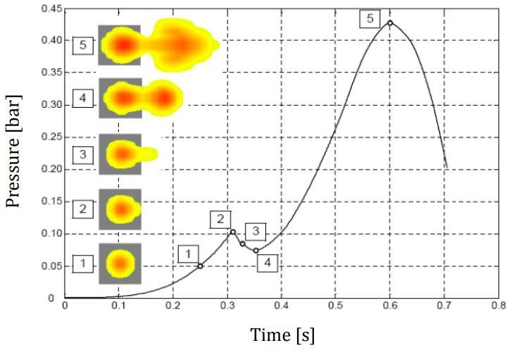
The ignition of a hydrocarbon gas-air cloud in a fully confined compartment might entail explosion pressures up to approximately 8 bars (800 kN/m2). Gas explosion in buildings, however, do not cause pressures of this magnitude. The main reasons are imperfect mixing of the gas-air cloud and the fact that these explosions are only partly confined. Windows, doors, light partition walls, or unrestrained brick walls act as venting elements, which, in case of failure provide explosion pressure relief. The table below culled from [1] gives typical failure pressures of these elements.
| Element | Typical failure pressure (kN/m2) |
| Glass windows | 2 – 7 |
| Room doors | 2 – 3 |
| Light partition walls | 2 – 5 |
| Breeze block walls (50 mm) | 4 – 5 |
| Unrestrained brick walls | 7 – 15 |
According to [2], key structural elements in a building should be designed to withstand the effects of an internal natural gas explosion, using a nominal equivalent static pressure, given by:
pd = 3 + pstat —— (1)
or
pd = 3 + 0.5pstat + 0.04/(Av/V)2 —— (2)
Whichever is greater.
Where;
pstat = uniformly distributed static pressure in kN/m2 at which venting components will fail,
Av is the area of venting components, and
V is the volume of the room.
This equation is found in Annex D of BS EN 1991-1-7:2004.
The venting components represent here the non-structural part of the enclosure (e.g. wall, floor, ceiling) with limited resistance that is intended to relieve the developing pressure from deflagration in order to reduce pressure on structural parts of the building. The explosive pressure acts effectively simultaneously on all of the bounding surfaces of the room. The expressions are valid for rooms up to a volume of 1000 m3 and venting areas over volume ratios of 0.05 m-1 ≤ Av/V ≤ 0.15 m-1.
An important issue is further raised in Clause 5.2 of EN 1991-1-7 [2]. It states that the peak pressures in the main text may be considered as having a load duration of 0.2 s. The point is that in reality, the peak will generally be larger, but the duration is shorter. So combining the loads from the above equations with a duration of 0.2 s seems to be a reasonable approximation.
For purpose of member design in the context of accidental actions, the Eurocode offers the following specific expression of the general formulation for design load combinations:
Ed = E(∑j≥1 Gk,j + P + Ad + (ψ1,1 or ψ2,1) ∙ Qk,1 + ∑i≥1 Ψ2,i ∙ Qk,i) —— (3)
Where:
Gk: Characteristic value of a permanent action
P: Representative value of a prestressing action
Ad: Design value of an accidental action
Qk: Characteristic value of a variable action
ψ1,1: Factor for the frequent value of a variable action
ψ2,1: Factor for the quasi-permanent value of a variable action
It should be noted that in comparison to the corresponding expression for persistent- or transient design situations no partial safety factors are to be applied to load effects within the accidental load combination. The design value of the accidental action is directly defined by means of a value Ad, which in practice often corresponds to a nominal value, such as in the case of gas explosions, where Ad is represented by a nominal, static equivalent pressure.
The reason for the use of nominal values is that a reliable statistical characterization of both occurrence and magnitude of accidental actions can only seldom be carried out because the available data is generally poor.
A Design Example of a Building for an Internal Explosion
Let us consider a kitchen on the first floor of a block of flats in Port Harcourt. The floor dimensions of the kitchen are 3 x 4 m while the storey height is 3m. The kitchen is characterised by a significant window and door opening of area 5 m2 (we are going to treat this as the venting area). Let us treat other walls in the kitchen as load-bearing.
This means that the volume V and the area of venting components Av for this case are given by:
Av = 5 m2
V = 3 × 4 × 3 = 36 m3
So the parameter Av/V can be calculated as:
Av/V = 5/36 = 0.138 m-1
As V is less than 1000 m3 and Av/V is well within the limits of 0.05 m-1 and 0.15 m-1 it is allowed to use the loads given in the code. The collapse pressure of the venting panels pstat is estimated as 4 kN/m2.
The equivalent static pressure for the internal natural gas explosion is given by:
pEd = 3 + pstat = 3 + 4 = 7 kN/m2
or
pEd = 3 + pstat/2 + 0.04/(Av/V)2 = 3 + (4/2) + 0.04/(0.138)2 = 7.1 kN/m2
Therefore, the design pressure should be taken as the highest, which in this case is 7.1 kN/m2
According to Eurocode EN 1990 (Basis of design), these pressures have to be combined with the self-weight of the structure and the quasi-permanent values of the variables loads. Let us consider the design consequences for the various structural elements.
Bottom floor
Let us start with the bottom floor of the kitchen. Let the self-weight of the floor and finishes be 4.95 kN/m2 and the imposed load 2 kN/m2 (ψ1 = 0.5 for considered category A). This means that the design load for the explosion is given by:
pEd = gk + Ad + ψ1qk = 4.95 + 7.1 + 0.5(2) = 13.05 kN/m2
The design for normal conditions is given by:
pEd = γGgk + γQqk = 1.35(4.95) + 1.5(2) = 9.68 kN/m2
According to [2], we should keep in mind that for accidental actions there is no need to use a partial factor on the resistance side. So for comparison, we could increase the design load for normal conditions by a factor of 1.2. The result could be conceived as the resistance of the structure against accidental actions, if it designed for normal loads only. Hence,
pRd = 1.2 x 9.68 = 11.616 kN/m2
Dynamic Increase in Load Bearing Capacity
It is now time to remember the clause in Annex B of Eurocode EN 1991-1-7. If we take into account the increase in short duration of the load we may increase the load-bearing capacity by a factor φd given by:
φd = 1 + √(gk/pRd) x √(2umax/g∆t2) —— (4)
Where;
gk = 4.95 kN/m2
pRd = 11.616 kN/m2
g = acceleration due to gravity = 9.81 m/s2
umax = 0.2 m (midspan deflection at collapse)
∆t = 0.2 seconds
φd = 1 + √(4.95/11.616) x √[(2 x 0.2)/(9.81 x 0.22)] = 1.652
pREd = φd pRd = 1.652 x 11.616 = 19.189 kN/m2 > 13.05 kN/m2
Therefore under the design condition, the bottom slab can be said to be fulfilling the design requirements.
Upper floor
Let us next consider the upper floor. Note that the upper floor for one explosion could be the bottom floor for the next one. The design load for the explosion, in that case, is given by (upward value positive!):
pEd = gk + Ad + ψ1qk = = – 4.95 + 7.1 + 0 = 2.15 kN/m2
So the load is small, but will give larger problems anyway. The point is that the load is in the opposite direction of the normal dead and live load. This means that the normal resistance may simply be close to zero. What we need is top reinforcement in the field and bottom reinforcement above the supports. So it will be normal to reinforce the floor slab top and bottom.
An important additional point to consider is the reaction force at the support. Note that the floor could be lifted from its supports, especially in the upper two stories of the building where the normal forces in the walls are small. In this respect, edge walls are even more vulnerable. The uplifting may change the static system for one thing and lead to different load effects, but it may also lead to freestanding walls. If the floor to wall connection can resist the lift force, one should make sure that the also the wall itself is designed for it.
Design of the walls/columns
Depending on the support condition of the walls/columns, the design pressure should be applied as a lateral load to the columns/walls, and the maximum bending moment determined. This should be combined with the axial force in the column/wall to determine the appropriate reinforcement.
References
[1] Hingorani R. (2017): Acceptable life safety risks associated with the effects of gas explosions on reinforced concrete structures. PhD thesis submitted to the Department of Civil Engineering, UNIVERSIDAD POLITÉCNICA DE MADRID
[2] Vrouwenvelder T., Diamantidid D. (2009): Accidental Actions (Chapter 5) in Load Effects on Buildings (Milan Hilicky et al Eds). CTU in Prague, Klokner Institute




Nice work my boss. I can’t wait to apply it.