The plate load test or ‘plate bearing test’ is one of the quickest ways of determining the bearing capacity and settlement characteristics of soils on site. This test is essentially useful especially for the design of shallow foundations such as pad footings.
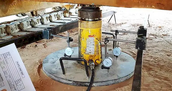
It basically consists of loading a rigid plate at the foundation level and increasing the load in arbitrary increments. The settlement corresponding to each load increment is recorded using at least two or three dial gauges with a least count of 0.02 mm. The gauges should be placed separately at 120° or 90° respectively. The test load is gradually increased till the plate starts to settle at a rapid rate. The load-settlement curve is plotted from which the settlement and bearing capacity of the soil can be determined.
The total value of the load on the plate divided by the area of the steel plate gives the value of the ultimate bearing capacity of soil. A factor of safety is applied to give the safe bearing capacity of soil.
The apparatus required for carrying out a plate load test are;
- Counterweight such as box or platform with heavy material such as concrete, steel, etc. The total counterweight should be at least 10% greater than the anticipated maximum test load.
- Hydraulic jack for applying the load
- Proving ring, 1 kg accuracy, for measuring the load
- Bearing Plate, 350mm, 450mm, and 600mm diameter
- Four dial gauges
- Reference beams.
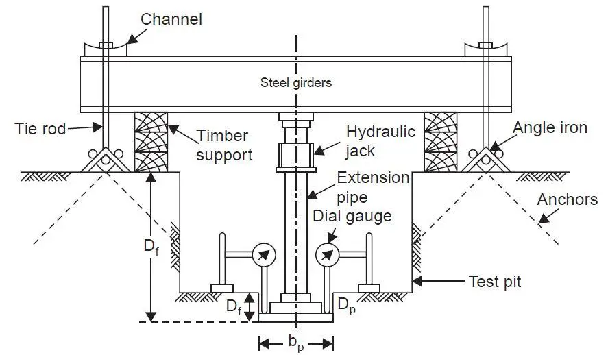
The procedure for carrying out plate load test according to BS 1377 part 9 are as follows;
- A circular plate having a maximum diameter of 300 – 600mm shall be used.
- Excavate to the test level as quickly as possible to minimise the effects of stress relief, particularly in cohesive fills. A mechanical excavator may be used provided that the excavator bucket does not have teeth and the last 100mm depth of excavation is carried out carefully by hand. If the test is performed in a test pit, the width of the pit should be at least 4 to 5 times of plate diameter.
- Carefully trim off and remove all loose material and any embedded fragments so that the area for the plate is generally level and as undisturbed as possible.
- Protect the test area and the apparatus from moisture changes, sunlight, and the effects of adverse weather as soon as the test level is exposed and throughout the test.
- The plate shall be placed on a thin layer (10 to 15 mm thick) of clean dry sand to produce a level surface on which to bed the plate.
- Set up the loading and deflection, measuring systems so that the load is applied to the plate without eccentricity and the deflection system is outside the zone of influence of the attachments. During these operations a small seating load may be applied to the plate to enable adjustments to be made: this seating load shall be less than 5 kN/m2.
- The load shall be applied in five increments. Settlement reading will be taken at 0.50 minute intervals for the first 2 minutes, and 1 minutes intervals thereafter, until the detectable movement of the plate has stopped, i.e. until the average settlement rate is less than 0.02 mm per 5 minute interval.
- At each increment, the pressure shall be maintained as near as possible constant.
- After the final test increment has been completed, the pressure in the hydraulic pump shall then be released and the settlement of the plate allowed to recover. When the recovery is essentially complete, the residual settlement value shall be recorded.
According to Venkatramiah (2006), great care shall be taken when interpreting the results from plate load test load-settlement curves. Typical curves obtained from load-settlement curves of plate load tests are shown in the figure below;
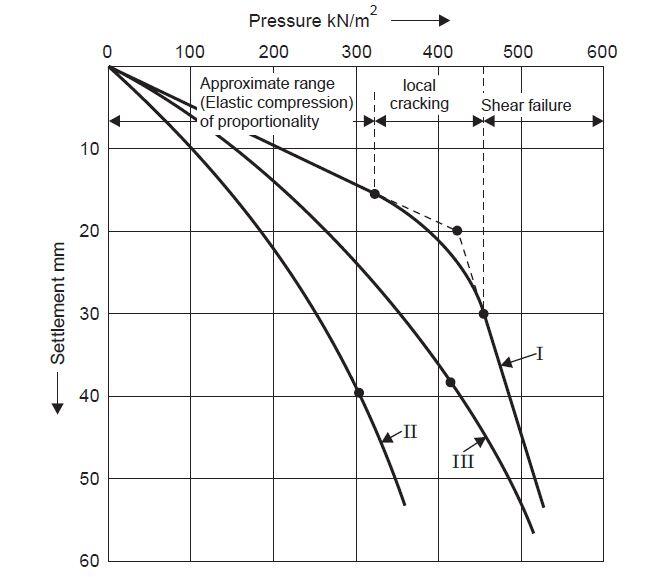
Curve I is typical of dense sand or gravel or stiff clay, wherein general shear failure occurs. The point corresponding to failure is obtained by extrapolating backward (as shown in the figure), as a pronounced departure from the straight-line relationship that applies to the initial stages of loading is observed. (This coincides approximately with the point up to which the range of proportionality extends).
Curve II is typical of loose sand or soft clay, wherein local shear failure occurs. Continuous steepening of the curve is observed and it is rather difficult to pinpoint failure; however, the point where the curve becomes suddenly steep is located and treated as that corresponding to failure.
Curve III is typical of many c – φ soils which exhibit characteristics intermediate between the above two. Here also the failure point is not easy to locate and the same criterion as in the case of Curve II is applied.
Thus, it is seen that, except in a few cases, arbitrary location of failure point becomes inevitable in the interpretation of load test results.
However, it is important to know that the plate load test has some drawbacks such as size effects, and does not take into account the possibility of consolidation settlement, especially in cohesive soils. Furthermore, it is reported that the load test results reflect the characteristics of the soil located only within a depth of about twice the width of the plate.
In this article we are going to show how to make computations from plate load test.
Example
A plate load test was conducted on a uniform deposit of sand at a depth of 1.5m below the natural ground level and the following data were obtained;
| Pressure (kPa) | 0 | 50 | 100 | 200 | 300 | 400 | 500 |
| Settlement (mm) | 0 | 2 | 4.5 | 10 | 17 | 30 | 50 |
The size of the plate was 600 mm × 600 mm and that of the pit 3.0 m × 3.0 m × 1.5 m.
(i) Plot the pressure-settlement curve and determine the failure stress.
(ii) A square footing, 1.5m × 1.5 m, is to be founded at 1.5 m depth in this soil.
Assuming the factor of safety against shear failure as 3.0 and the maximum permissible settlement as 25 mm, determine the allowable bearing pressure.
(iii) Design of footing for a load of 600 kN, if the water table is at a great depth.
Solution
(1) The pressure-settlement curve is shown in the figure below. The failure point is obtained as the point corresponding to the intersection of the initial and final tangents. In this case, the failure pressure is 335 kN/m2.
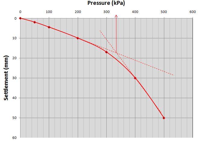
The ultimate bearing capacity from the plate load test qult,bp = 335 kN/m2
Applying correction for sandy soil deposit and a footing of width 1.5m;
qult,f = qult,bp x (Width of foundation)/(Size of the base plate) = 335 x (1.5/0.6) = 837.5 kN/m2
Applying a factor of safety of 3.0 against shear failure;
qa = qult,f/FOS = 837.5/3 = 279.16 kN/m2
Alternatively;
Equate the value of qult,bp to 0.5γbpNγ
Where;
bp = size of the base plate = 600 mm
γ = density of soil (say 18.5 kN/m3)
Nγ = Bearing capacity factor (to be determined)
335 = 0.5 x 18.5 x 0.6 x Nγ
On solving, Nγ = 60.36
This reflects to an angle of internal friction (Φ) of about 36.5° using Terzaghi’s theory. The corresponding value of Nq is 50.48.
For a square footing of width (B) and depth (Df) 1.5m founded on sand;
qult = qNq + 0.4γBNγ = (18.5 x 50.48) + (0.4 x 18 x 1.5 x 60.36) = 1585.768 kN/m2
qa = qult/FOS = 1585.768/3 = 528.589 kN/m2
From settlement consideration;
Sp = S[bp(b + 0.3)/b(bp + 0.3)]2
Sp = 25[0.6(1.5 + 0.3)/1.5(0.6 + 0.3)]2 = 16 mm
From the load settlement curve, this settlement corresponds to a pressure of 290 kN/m2
For this particular case study, settlement will govern the design.
The maximum allowable service column load on a 1.5m x 1.5 m square pad footing will therefore be (1.5 x 1.5 x 290) = 652.5 kN. This shows that a column load of 600 kN can be safely supported on a footing of 1.5 m x 1.5m on the soil.
References
(1) BS 1377-9:1990 – Methods for test for soils for civil engineering purposes – In-situ tests. British Standard Institution
(2) Venkatramaiah C. (2006): Geotechnical Engineering (3rd Edition). New Age Publishers, New Delhi, India




Great article, well written.
Great
Molto chiaro. complimenti. Utilissimo.
Respect to your effort, thank you.
Hi author,
For the last part of the calculation, you have considered 290 kN/m2 as the allowable bearing pressure. But allowable bearing pressure should be the minimum of safe bearing pressure (279.16 kN/m2, based on FOS of ultimate bearing capacity) and the bearing capacity for the permissible settlement (25mm) which is 290 kN/m2. Therefore here allowable bearing capacity is 279.16 kN/m2. So my question is why did you use 290 kN/m2 instead of 279.16kN/m2 to calculate the load force the soil can resist?