The most widespread alternative for roof construction in Nigeria is the use of trusses, of which timber and steel are the primary choices of materials. An advantage of using trusses for roofs is that ducts and pipes that are required for the operation of the building’s services can be installed through the truss web. However, careful attention must be paid to the design of the truss members and their connection (which may be welded or bolted) since their failure can be catastrophic both in terms of loss of life and economy.
The roof of a church building in Uyo, Akwa Ibom State, Nigeria collapsed on the 10th of December 2016 and left more than 60 worshippers dead, and many injured. This is to show how important, and why engineers must pay careful attention to such design situations. The aim of this article is to show in the clearest manner, how steel truss members can be designed according to EN 1993-1-1-:2005 (Eurocode 3) design code.
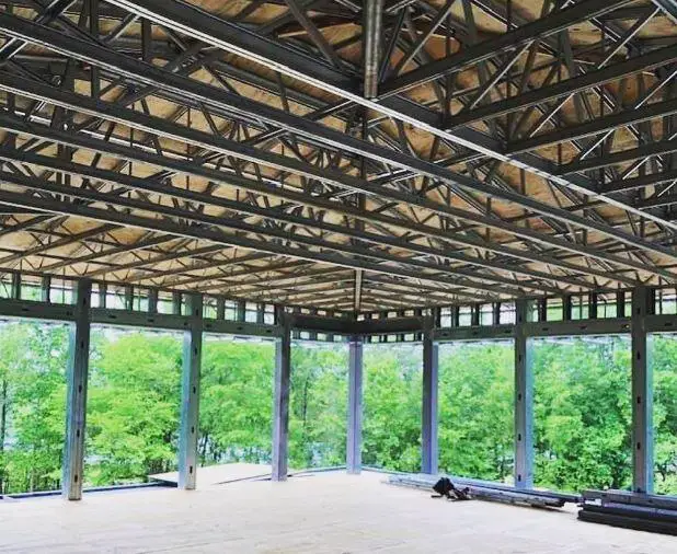
A truss is basically a system of triangulated members that are connected and designed to carry load. A truss is inherently stable in shape and resists load by developing primarily axial forces which might be tensile or compressive in nature. The connections in trusses are always assumed to be nominally pinned. When the connection of trusses is stiff, secondary effects such as bending moment and shear force are induced in the truss members.
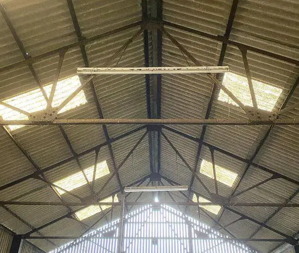
For a good structural performance of roof trusses, the ratio of span to truss depth should be in the range of 10 to 15. However, it should be noted that the architectural design of the building determines its external geometry and governs the slope given to the top chord of the truss.
For the design of a compression member in a roof truss, several buckling modes need to be considered. In most truss members, only flexural buckling of the compressed members in the plane of the truss structure and out of the plane of the truss structure need to be evaluated. The flexural buckling in Eurocode 3 is achieved by applying a reduction factor to the compression resistance.
Example on the Design of Steel Roof Trusses
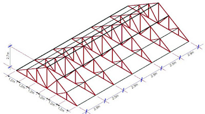
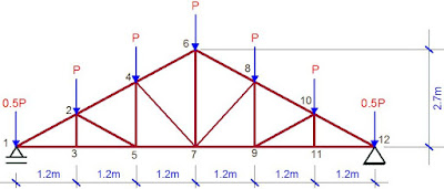
To illustrate this, a simple design example has been presented. The skeletal structure of a roof system (18.0m long and 7.2m wide) is as shown in the Figure below. The truss is made up of Howe Truss configuration spaced at 3m intervals. It is desired to specify the appropriate angle sections that will safely carry the anticipated loading using Eurocode design code (Specified steel grade S 275).
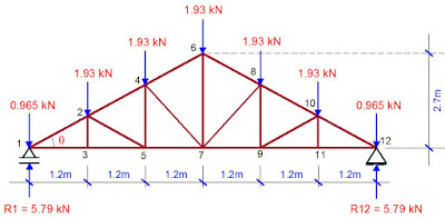
The idealised 2D model of the roof truss typical loading configuration is as shown below;
Load Analysis
Span of roof truss = 7.2m
Spacing of the truss = 3.0m
Nodal spacing of the trusses = 1.2m
Permanent (dead) Loads
Self-weight of long span aluminium roofing sheet (0.55mm gauge thickness) = 0.019 kN/m2
Weight of ceiling (adopt 10mm insulation fibre board) = 0.077 kN/m2
Weight of services = 0.1 kN/m2
Weight of purlin (assume CH 150 x 75 x 18 kg/m) = (18 x 3m)/(1.2 x 3) = 15 kg/m2 = 0.147 kN/m2
Self weight of trusses (assume) = 0.2 kN/m2
Total deal load (gk) = 0.536 kN/m2
Therefore the nodal permanent load (gk) = 0.536 kN/m2 × 1.2m × 3m = 1.9296 kN
Variable (Imposed) Load
Category of roof = Category H – Roof not accessible except for normal maintenance and repairs (Table 6.9 EN 1991-1-1:2001)
Imposed load on roof (qk) = 0.75 kN/m2
Therefore the nodal variable load (QK) = 0.75 kN/m2 × 1.2m × 3m = 2.7 kN
Wind Load
Wind velocity pressure (dynamic) is assumed as = qp(z) = 1.5 kN/m2
When the wind is blowing from right to left, the resultant pressure coefficient on the windward and leeward slopes with positive internal pressure (cpe) is taken as −0.9
Therefore the external wind pressure normal to the roof is;
qe = qpcpe = −1.5 × 0.9 = 1.35 kN/m2
Vertical component pev = qe cos θ = 1.35 × cos 36.869 = 1.08 kN/m2 acting upwards ↑
Therefore the nodal wind load (Wk) = 1.08 kN/m2 × 1.2m × 3m = 3.888 kN
To see how wind load is analysed using Eurocode, click HERE
Analysis of the Truss for Internal Forces
N/B: Please note that the internal forces in the members are denoted by Fi-j which is also equal to F j-i e.g. F 2-3 = F 3-2 ; so kindly distinguish this from other numeric elements
Dead Load
JOINT 1
θ = tan-1(2.7/3.6) = 36.869
Let ∑Fy = 0
5.79 – 0.956 + F1-2 (sin θ) = 0
F1-2 = (-4.834)/sin36.869 = -8.0568 kN (COMPRESSION)
Let ∑Fx = 0
F1-2 (cos θ) + F1-3 = 0
F1-3 = -(-8.0568 ×(cos36.869)) = 6.445 kN (TENSION)
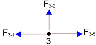
JOINT 3
Let ∑Fy = 0
F3 – 2 = 0 (NO FORCE)
Let ∑Fx = 0
F3–5 – F3–1 = 0
F3–1 = F3–5 = 6.445 kN (TENSION)
JOINT 2
ϕ = tan-1(0.9/1.2) = 36.869 = θ
Let ∑Fy = 0
-1.93 + F2-4(sin θ) – F2–3 – F2-5(sin θ) – F2-1(sin θ) = 0
-1.93 + F2-4(sin 36.869) – 0 – F2-5(sin 36.869) – [-8.0568(sin 36.869)] = 0
0.6 F2–4 – 0.6F2–5 = -2.904 ———- (1)
Let ∑Fx = 0
F2-4(cos θ) + F2-5(cos θ) – F2-1(cos θ) = 0
F2-4(cos 36.869) + F2-5(cos 36.869) – [-8.0568(cos36.869)] = 0
0.8 F2–4 + 0.8 F2–5 = -6.4455———- (2)
Solving equations (1) and (2) simultaneously;
F2-4 = – 6.448 kN (COMPRESSION)
F2-5 = -1.608 kN (COMPRESSION)
JOINT 5
Let ∑Fy = 0
F5-2(sin ϕ) + F5–4 = 0
-1.608 (sin 36.869) + F5–4 = 0
F5–4 = 0.9646 kN (TENSION)
Let ∑Fx = 0
–F5–3 – F5–2 (cos ϕ) + F5–7 = 0
-6.445– [–1.608 (cos 36.869)] + F5–7 = 0
F5–7 = 5.1586 kN (TENSION)
JOINT 4
α = tan-1(1.8/1.2) = 56.309°
Let ∑Fy = 0
-1.93 – F4–2 (sin θ) – F4–5 – F4–7 (sin α) + F4–6(sin θ) = 0
-1.93 – [-6.448(sin 36.869)] – 0.9646 – F4-7 (sin 56.309) + F4–6 (sin 36.869) = 0
-0.832 F4–7 + 0.6 F4–6 = -0.9742 ——– (3)
Let ∑Fx = 0
F4–7 (cos α) + F4-6(cos θ) – F4-2(cos θ) = 0
F4-7(cos 56.309) + F4-6(cos 36.869) – (-6.448(cos36.869)) = 0
0.5547 F4–7 + 0.8 F4–6 = – 5.1584 ——– (4)
Solving equations (3) and (4) simultaneously;
F4-7 = – 2.319 kN (COMPRESSION)
F4-6 = -4.8398 kN (COMPRESSION)
JOINT 6
Let ∑Fx = 0
– F4-6(cos θ) + F6-8 (cos θ) = 0
-(-4.8398 cos 36.869) + F6-8 (cos 36.869) = 0
F6-8 = (-3.87184)/cos 36.869 = – 4.8398 kN (COMPRESSION)
Let ∑Fy = 0
-1.93 – F6–4 (sin θ) – F6–7 – F6–8 (sin θ) = 0
-1.93 – [-4.8398(sin 36.869)] – F6–7 – [–4.8398(sin 36.869)] = 0
F6–7 = 3.8777 kN (TENSION)
SUMMARY OF RESULTS FOR DEAD LOAD (GK)
BOTTOM CHORD
F1-3 = 6.445 kN (T)
F3-5 = 6.445 kN (T)
F5-7 = 5.158 kN (T)
TOP CHORD
F1-2 = -8.0568 kN (C)
F2-4 = -6.448 kN (C)
F4-6 = -4.839 kN (C)
VERTICALS
F2-3 = 0 (NO FORCE)
F4-5 = 0.9646 kN (T)
F6-7 = 3.877 kN (T)
DIAGONALS
F2-5 = -1.608 kN (C)
F4-7 = – 2.319 kN (C)
Similarly, the summary of analysis results for imposed load (Qk) is given below;
BOTTOM CHORD
F1 – 3 = 8.992 kN (T)
F3 – 5 = 8.992 kN (T)
F5 – 7 = 7.198 kN (T)
TOP CHORD
F1 – 2 = -11.241 kN (C)
F2 – 4 = – 8.998 kN (C)
F4 – 6 = -6.748 kN (C)
VERTICALS
F2 – 3 = 0 (NO FORCE)
F4 – 5 = 1.346 kN (T)
F6 – 7 = 5.391 kN (T)
DIAGONALS
F2 – 5 = -2.242 kN (C)
F4 – 7 = – 3.238 kN (T)
Summary of Results for Wind Load (Wk)
BOTTOM CHORD
F1 – 3 = -12.948 kN (C)
F3 – 5 = -12.948 kN (C)
F5 – 7 = -10.365 kN (C)
TOP CHORD
F1 – 2 = 16.187 kN (T)
F2 – 4 = 12.957 kN (T)
F4 – 6 = 9.717 kN (T)
VERTICALS
F2 – 3 = 0 (NO FORCE)
F4 – 5 = – 1.938 kN (C)
F6 – 7 = -7.763 kN (C)
DIAGONALS
F2 – 5 = 3.228 kN (T)
F4 – 7 = 4.662 kN (T)
In all cases, (T) – Tensile force; (C) – Compressive force
Structural Design of Roof Trusses to Eurocode 3
All structural steel employed in the design has the following properties;
fy (Yield strength) = 275 N/mm2
fu (ultimate tensile strength = 430 N/mm2)
Design of the bottom chord (considering maximum effects)
LOAD CASE 1: DEAD LOAD + IMPOSED LOAD only
Fu = γGjGk + γQkQk
Ultimate design force (NEd) = 1.35Gk + 1.5Qk
NEd = 1.35(6.445) + 1.5(8.992) = 22.189 kN (TENSILE)
LOAD CASE 2: DEAD LOAD + WIND LOAD acting simultaneously
Partial factor for permanent actions (DK) = γGj = 1.0 (favourable)
Partial factor for leading variable actions (Wk) = γWk = 1.5
Therefore ultimate design force in the member = Fu = γGjGk + γWkWk = Gk + 1.5Wk.
NEd = 1.0(6.445) – 1.5(12.894) = -12.896 kN (COMPRESSIVE)
Therefore, all bottom chord members should be able to resist an axial tensile load of 22.189 kN and a possible reversal of stresses with a compressive load of 12.896 kN
Length of longest bottom chord member = 1200mm
Consider EQUAL ANGLES UA 50 X 50 X 6
Gross Area = 5.69 cm2
Radius of gyration (axis y-y) ri = 1.5 cm
Considering one M12 bolt (14mm diameter allowance) – Equivalent tension area = 3.72 cm2
Equivalent tension area for welded connection = 4.88cm2
Nt,Rd is the lesser of;
(Anet × Fy)/γM0 and (0.9Anet × fu)/γM2
fu = 430 N/mm2; fy = 275 N/mm2
Nt,Rd = (3.72 × 102 × 275)/1.0 × 10-3) = 102.3 kN
Also check; (0.9 × 3.72 × 102 × 430)/1.25 × 10-3 = 115.17 kN
Therefore;
NSd/Nt,Rd = 22.189/102.3 = 0.216 < 1.0 (Section is ok for tension resistance)
Compression and buckling resistance
Thickness of section t = 6 mm. Since t < 16mm, Design yield strength fy = 275 N/mm2 (Table 3.1 EC3)
Section classification
ε = √(235/fy) = √(235/275) = 0.9244
h/t = 50/6 = 8.33.
Referring to Table 5.2 (sheet 3) of Eurocode 3, Part 1-1, for class 3 classification,
h/t ≤ 15ε and (h + b)/2t ≤ 11.5ε. In our case,
5ε = 15 × 0.92 = 13.8 > h/t (8.3) OK
(h + b)/2t = 8.33 < 10.8 (11.5 × 0.92) OK
Thus, the section satisfies both of the conditions.
Resistance of the member to uniform compression
NC,Rd = (A × Fy)/γM0 = (5.69 × 102 × 275)/1.0 = 156475 N = 156.475 kN
NEd/NC,Rd = 12.896/156.475 = 0.0824 < 1 Therefore section is ok for uniform compression.
Buckling resistance of the member
Since the member is pinned at both ends, critical buckling length is the same for all axis; Lcr = 1200mm
Slenderness ratio λ = Lcr/(ri × λ1)
λ1= 93.9ε = 93.9 × 0.9244 = 86.801
In the planar axis (z-z and y-y)
λ = 1200/(15 × 86.801) = 0.9216
Buckling curve b is appropriate for all angle sections according to Table 6.2 of Eurocode 3
α = 0.34 for buckling curve b
Φ = 0.5 [1 + α(λ – 0.2) + λ2]
Φ = 0.5 [1 + 0.34(0.9216 – 0.2)+ 0.92162] = 1.0473
X = 1/[Φ + √(Φ2 – λ2)]
X = 1/[1.0473 + √(1.0472 – 0.92162)] = 0.6473 < 1
Therefore Nb,Rd = (X × A × fy)/γm1 = (0.6473 × 5.69 × 102× 275)/1.0 = 101286.2675 N = 101.286 kN
NEd/Nb,Rd = 12.869/101.286 = 0.127 < 1 Therefore the section is ok for buckling
Therefore, UA 50 x 50 x 6 is ok to resist all axial loads on the bottom chord of the truss.
Following the method shown above in section 4.0, other members of the truss can be efficiently designed.
Thank you for visiting
TO DOWNLOAD THE FULL DESIGN PAPER IN PRINTABLE PDF FORMAT, CLICK HERE










Very educative!! Well done bro_!
Very good
Thank you Afam
Thank you
Uba my man! Pls make a simple duplex design with staadpro… thanks
well written. thank you
A job well done
Nice presentation. I have a question though: When designing for roof trusses in Nigeria, is 0.75 Kn/m2 a reasonable imposed load to adopt? What could possibly create such a load? Thanks
The code gives some specific guidelines, and range of possible imposed loads. I know in Nigeria it may be hard to imagine what will generate such load, but going to the roof for repairs and maintenance, or even the effect of rain can be seen as imposed load.
Though these kits come with highly competent equipment, there are certain precautions stated in the product manuals of such products which need to be followed for user's safety.
Installation of an expert. Sure the art, such that the ratio is held firmly and is installed in the roof of his own affection.
Roof repairing is one of the hardest work of the home, for that you have to choose right servicer
Slip-ups in rooftop repairs or establishments will prompt the need of supplanting the framework once more, in this way the need to spend more money. Extra costs can be evaded by procuring a solid roofing organization.
Very nice presentation. Do you by any chance have design calculations for the connections? Thanks.
However, it is tricky business and you can never know how much a roof repair job is going to cost you and that is the very reason that you need to estimate the roof repair job before hiring a professional roofing company.
• I will dеfinitelydigg it and personally suggest to my friends. I’m sure thеywilⅼ be benefited from thiѕ web site.
More established homes frequently have lengths of 2" x 6" introduced rather than pressed wood or OSB board.
This design is lacking in two main ways:
1. Eurocode for wind loading doesn't allow us to use a uniform distributed load over the whole roof. There are multiple uneven wind load scenarios to be calculated.
2. Buckling resistance has been calculated in the vertical planes but not the horizontal planes. Without cross-bracing between trusses, they could buckle sideways as you effectively have a critical buckling length of 7.2m on the bottom elements and 4.5m on the top. Perhaps you have assumed the purlins will prevent this, but this is insufficient without cross-bracing.
1. The U.K national anex allow the use of a factor for calculating the overall wind load on a roof or building. Thus the wind load may be considered to be constant over the entire structure by multiplying with the overall cp’s values.
2. The trusse are so closely spaced for buckling in the horizontal plane to be a issue
I diagree your reply. You are wrong.
Buckling in the horizontal plane will clearly be an issue if wind load uplift is strong enough.
You should not rely on such demonstration and contact a professional engineering office.
This is my first time i visit here. I found so many interesting stuff in your blog especially its discussion. From the tons of comments on your articles, I guess I am not the only one having all the enjoyment here keep up the good work
I want to express my gratitude for your support.
Roof pitches are typically measured by an equation called the "rise over the run" and is figured in the number of feet that the roof rises in a 12 foot horizontal run. A "12/12 pitched roof" means that the roof rises 12 feet in a horizontal run of 12 feet and results in a 45 degree angle.
Me and my companions have completely delighted in this blog.
I can set up my new idea from this post. It gives in depth information. Thanks for this valuable information for all,..
The home roofing job is the most critical of them all. Proper protection for your house depends on the right roofing techniques. You need to choose the right roofing materials for the particular climatic condition you have in your area of living.
1. The U.K national anex allow the use of a factor for calculating the overall wind load on a roof or building. Thus the wind load may be considered to be constant over the entire structure by multiplying with the overall cp’s values.
2. The trusse are so closely spaced for buckling in the horizontal plane to be a issue
Couldn’t find the overall wind load factor in U.K national annex.
Thanks very much
am new person to visit this and I am impressed
Excellent!!, you work is always good and clear
How can build wooden trusses 50ft by 60ft the higth is 2m
Thanks very much
Seeing your example of how a roof truss works really does help me a lot with planning things out. Since we’re building our house from the ground up, I can definitely see how getting this kind of concept right will pay off quite a lot. If I can find a truss expert in the area, I’ll ask them for a model like this for sure so things can go well.
Nice work. What about the design of connections?