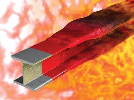
In the event of a fire, the general objectives of fire protection of structures are to limit hazards to individuals and society, adjacent property, and, where necessary, the environment or immediately exposed property (EN 1993-1-2:2005). The relevant time of fire exposure during which the associated fire resistance function of a structure is maintained despite fire actions is characterized as fire resistance in terms of time. Therefore, the fire resistance design of steel beams is concerned with maintaining the load-bearing function, integrity separating function, and thermal insulating separating function of a steel beam for a given period of time.
According to the Construction Products Directive 8911 06/EEC, the following are the essential requirement for the limitation of fire risks:
“The construction works must be designed and built in such a way, that in the event of an outbreak of fire;
- the load bearing resistance of the construction can be assumed for a specified period of time
- the generation and spread of fire and smoke within the works are limited
- the spread of fire to neighbouring construction works is limited
- the occupants can leave the works or can be rescued by other means
- the safety of rescue teams is taken into consideration”.
According to the European standards, three major criteria are used to define the fire resistance of structures:
R – load-bearing function
E – integrity separating function
I – thermal insulating separation function
It is important to note that the above criteria may be required individually or in combination:
• separating only: integrity (criterion E) and, when requested, insulation (criterion I)
• load bearing only: mechanical resistance (criterion R)
• separating and load-bearing: criteria R, E and, when requested I
Where mechanical resistance in the case of fire is required, steel structures shall be designed and constructed in such a way that they maintain their load-bearing function the relevant fire exposure. Criterion “R” is assumed to be satisfied in steel beams where the load-bearing function is maintained during the required time of fire exposure.
For a given load level, the temperature at which failure is expected to occur in a structural steel element for a uniform temperature distribution is called the critical temperature (θcrit). The thermal action on the steel member is a result of the heat flux transferred from the fire to the steel member. This is usually regarded as an indirect action.
The load bearing function of a structure is satisfied only if during the relevant duration of fire exposure t;
Efi,d,t ≤ Rfi,d,t
where
Efi,d,t: design effect of actions (Eurocodes 0 and 1)
Rfi,d,t: corresponding design resistance of the structure at instant t
It is however important to note that Eurocode permits the fire resistance of steel structures to be assessed in any of these three domains;
Time; tfi,d ≤ tfi,req (this usually feasible using advanced computational models)
Load Resistance; Efi,d,t ≤ Rfi,d,t (This approach is feasible by hand calculation. Find reduced resistance at required resistance time)
Temperature; θcr,d ≤ θd (The most simple approach, find the critical temperature for loading, compare with design temperature)
For ordinary structural fire structural design of steel beams, simple calculation models such as critical temperature can be used.
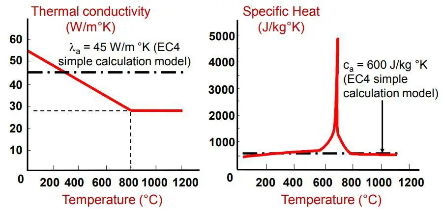
The thermal properties of structural steel at elevated temperature is shown below. At about 600°C, the elastic modulus of elasticity of steel is reduced by about 70% while the yield strength reduces by about 50%.
Under fire situation, the design loading is given by;
Efi,d,t = ∑Gk,j + ψ2,1Qk,1 + ∑ψ2,1Qk,I
More commonly, a reduction factor ηfi is applied to the loading under ambient conditions in order to represent the loading under fire conditions. This is given by;
Efi,d,t = ηfiEd
ηfi = Efi,d,t/Rd

In ambient temperature strength design;
γG = 1.35 (Permanent loads)
γQ.1 = 1.50 (Combination factor; variable loads)
In structural fire design
γGA = 1.0 (Permanent loads; accidental design situations)
γ2.1 = 0.3 (Combination factor; variable loads, offices)
Steps in the Fire Resitance Design of Steel Beams
The following are the steps to follow when assessing the fire resistance design of steel beams;
(1) Evaluate the actions on the structuture in fire situation Efi.d. This is commonly achieved by applying a reduction factor to the ambient temperature load.
(2) Classify the member under class 1, class 2, class 3 or class 4 depending the rotation capacity using EC3 guidelines
(3) Evaluate the resistance of the structure at ambient temperature (20°C) by fire rules Rfi.d.20.
(4) Calculate the degree of utilisation μ0
(5) Calculate the critical temperature θcr
(6) Calculate the section factor Am/V and the correction factor ksh
(7) Carry out step by step calculation to verify if θfi,d = θcr at the time of fire exposure tfi,d
(8) Check if tfi,d is greater than the required fire resistance period of the structure treq
Design Example of Fire Resistance of Steel Beams
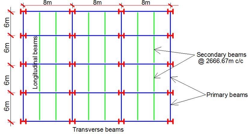
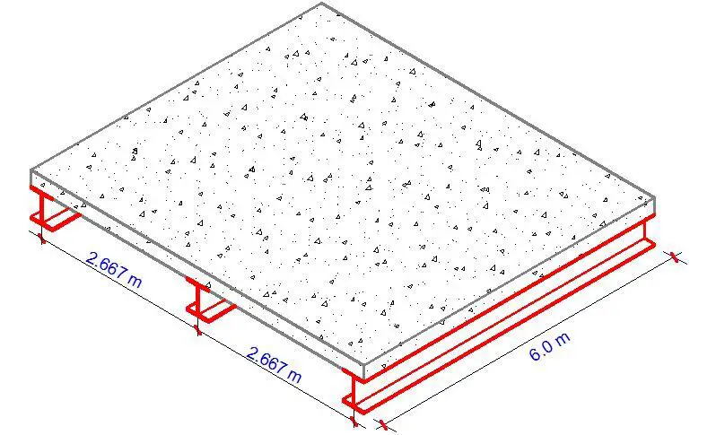
Verify the fire resistance of an intermediate secondary beam (S275) in an office block supporting a slab of 175 mm thickness. The expected fire rating is 30 minutes. The slab is to support a variable action of 3 kN/m2, and finishes of 1.5 kN/m2.
Design Data
Imposed variable load qk = 3.0 kN/m2
Thickness of R.C. slab = 150 mm
Finishes = 1.5 kN/m2
Analysis and Design at Normal Room Temperature
Permanent loads
Unit weight of reinforced concrete = 25 kN/m3
Thickness of slab = 150 mm = 0.15 m
Self weight of slab = 25 × 0.15 = 3.75 kN/m2
Weight of finishes = 1.5 kN/m2
Total permanent actions (gk) = 5.25 kN/m2
Variable Actions
Imposed variable load = 3.0 kN/m2
Total live load (qk) = 3.0 kN/m2
Normal Temperature Design of the Secondary Beam
The load transferred from the slab to the secondary beams considering a bay width of 2.667m
At ultimate limit state (neglecting reduction factors);
PEd = 1.35gk + 1.5gk
PEd = 1.35(5.25) + 1.5(3) = 11.6 kN/m2
Ultimate load transferred to every secondary beam;
Fd = 11.6 kN/m2 × 2.667m = 30.937 kN/m
Self weight of beam = 1.35 × 0.392 = 0.528 kN/m
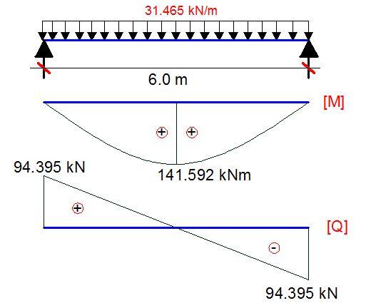
Total design load on the beam = 30.937 + 0.528 = 31.465 kN/m
My,Ed = (Fd.L2)/8 = (31.465 × 62)/8 = 141.592 kNm
VEd = (Fd.L)/2 = (31.465 × 6)/2 = 94.395 kN
An advanced UK beam S275 is to be used for this design.
fy = 275 N/mm2
γm0 = 1.0 (Clause 6.1(1) NA 2.15 BS EN 1993-1- 1:2005)
The required section is supposed to have a plastic modulus about the y-y axis that is greater than;
Wpl,y = My,Ed.γm0/fy
Wpl,y = (150.093 × 103 × 1.0)/275 = 545.792 cm3
From steel tables, try section UB 305 x 165 x 40 Wpl,y = 623 cm3
Properties
h = 303.4 mm; b = 165 mm; d = 265.2 mm; tw = 6.0 mm; tf = 10.2 mm; r = 8.9 mm; A = 51.3 cm4; Iy = 8500 cm4; Iz = 764 cm4; Wel,y = 560 cm3;
hw = h – 2tf = 265.2 mm
E (Modulus of elasticity) = 210000 N/mm2 (Clause 3.2.6(1))
Classification of section
ε = √(235/fy) = √(235/275) = 0.92 (Table 5.2 BS EN 1993-1- 1:2005)
Outstand flange: flange under uniform compression c = (b – tw – 2r)/2 = [165 – 6 – 2(8.9)]/2 = 70.6 mm
c/tf = 70.6/10.2 = 6.921
The limiting value for class 1 is c/tf ≤ 9ε = 9 × 0.92
5.03 < 8.28
Therefore, outstand flange in compression is class 1
Internal Compression Part (Web under pure bending)
c = d = 265.2 mm
c/tw = 265.2/6 = 44.2
The limiting value for class 1 is c/tw ≤ 72ε = 72 × 0.92 = 66.24
44.2 < 66.24
Therefore, the web is plastic. Therefore, the entire section is class 1 plastic.
Member Resistance Verification
Moment Resistance
For the structure under consideration, the maximum bending moment occurs where the shear force is zeo. Therefore, the bending moment does not need to be reduced for the presence of shear force (clause 6.2.8(2)).
MEd/Mc,Rd ≤ 1.0 (clause 6.2.5(1))
Mc,Rd = Mpl,Rd = (Mpl,y × Fy)/γm0
Mc,Rd = Mpl,Rd = [(623 × 275)/1.0] × 10-3 = 171.325 kNm
MEd = 141.592 kNm
MEd/Mc,Rd = 141.592/171.325 = 0.825 < 1.0 Ok
Shear Resistance (clause 6.6.2)
The basic design requirement is;
VEd/Vc,Rd ≤ 1.0
Vc,Rd = Vpl,Rd = Av(Fy / √3)/γm0 (for class 1 sections)
For rolled I-section with shear parallel to the web, the shear area is;
Av = A – 2btf + (tw + 2r)tf (for class 1 sections) but not less than ηhwtw
Av = (51.3 × 10² – (2 × 165 × 10.2) + [6 + 2(8.9)] × 10.2 = 2006.76 mm2
η = 1.0 (conservative)
ηhwtw = (1.0 × 265.2 × 6) = 1591.2 mm2
2006.76 > 1591.2
Therefore, Av = 2006.76 mm2
The shear resistance is therefore;
Vc,Rd = Vpl,Rd = [2006.76 × (275/ √3)/1.0] × 10-3 = 318.6159 kN
VEd/Vc,Rd = 94.395/318.62 = 0.296 < 1.0 Ok
Shear Buckling
Shear buckling of the unstiffnened web will not need to be considered if;
hw/tw ≤ 72ε/η
hw/tw = 265.2/6 = 44.2
72ε/η = (72 × 0.92)/1.0 = 66
44.2 < 66 Therefore shear buckling need not be considered.
Serviceability limit state
Vertical deflections are computed based on unfactored variable loads. Permanent loads need not be considered (BS EN 1993-1-1 NA 2.23)
qk = 3.0 × 2.667 = 8 kN/m
w = 5ql4/384EI
w = (5 × 8 × 60004)/(384 × 210000 × 8500 × 104) = 7.563 mm
Span/360 = 6000/360 = 16.667 (BS EN 1993-1-1 NA 2.23)
7.563 < 16.667
Therefore, deflection is satisfactory
Fire Design of the Secondary Beam

The loading due to fire design is given by;
Efi,d,t = ∑Gk,j + ψ2,1Qk,1 + ∑ψ2,1Qk,I
As a simplification to the loading above, the fire part of EC 3 permits us to apply a reduction factor ηfi to the load of normal temperature design.
ηfi = (γGAGk + ψ2,1 Qk,1)/(γGGk + γQQk,1)
For the secondary beams;
Gk = 5.25 × 2.667 = 14.0 kN/m
Qk = 3.0 × 2.667 = 8.0 kN/m
ψ2,1 = 0.3
γG = 1.35
γGA = 1.0
γQ = 1.5
ηfi = [14 + (0.3 × 8)] / [(1.35 × 14) + (1.5 × 8)] = 0.53
Bending moment; Mfi,d,t = 0.53MEd = 0.53 × 141.592 = 75 kNm
Shear force; Vfi,d,t = 0.53VEd = 0.53 × 94.395 = 50 kN
According to equation 4.2 of EN 1993-1-2 for fire resistance design;
ε = 0.85√(235/fy) = 0.786 for S275 grade of steel
Outstand flange: flange under uniform compression c = (b – tw – 2r)/2 = [165 – 6 – 2(8.9)]/2 = 70.6 mm
c/tf = 70.6/10.2 = 6.921
The limiting value for class 1 is c/tf ≤ 9ε = 9 × 0.786
(c/tf)5.03 < (9ε) 7.074
Therefore, outstand flange in compression is class 1
Internal Compression Part (Web under pure bending)
c = d = 265.2 mm
c/tw = 265.2/6 = 44.2
The limiting value for class 1 is c/tw ≤ 72ε = 72 × 0.786 = 56.592
44.2 < 56.592
Therefore, the web is plastic. Therefore, the entire section is class 1 plastic under fire loading.
From our calculations for normal temperature design, it can be verified that;
Mc,Rd = Mpl,Rd = 171.325 kNm
Vc,Rd = Vpl,Rd = = 318.6159 KN
From relation 4.24 of EN 1993-1-2;
We can calculate the utilisation ratio of the unprotected steel beam;
With respect to bending moment;
μ0,m = ηfi (γm,0/γm,fi) = (Mfi,d,t/MRd) × (γm,0/γm,fi) = (75/171.325) × (1.0/1.0) = 0.437 < 1.0
With respect to vertical shear;
μ0,v = ηfi (γm,0/γm,fi) = (Vfi,d,t/VRd) × (γm,0/γm,fi) = (50/318.6159) × (1.0/1.0) = 0.156 < 1.0
As the beam supports the concrete slab above, the impact of the kappa factors relative to the temperature gradient over its depth have to be taken into account. However, they have an impact on bending moment alone. No rule is provided for shear.
The modified degree of utilisation for bending moment;
κ1 = 1.0
κ2 = 1.0
For the unprotected beam having all four sides exposed – clause 4.1(16) of EN 1993-1-2
μ0,m,k = μ0,m(κ1 κ2) = 0.463 × (1.0 × 1.0) = 0.463
The modified degree of utilisation factor for vertical shear
μ0,v,k = μ0,v = 0.166
μ0 = max (μ0,m,k; μ0,v,k)
μ0 = max (0.463; 0.166) = 0.463
Calculation of the critical temperature of the unprotected beam;
Using simplified equation from Equation 4.22 of EN 1993-1-2;
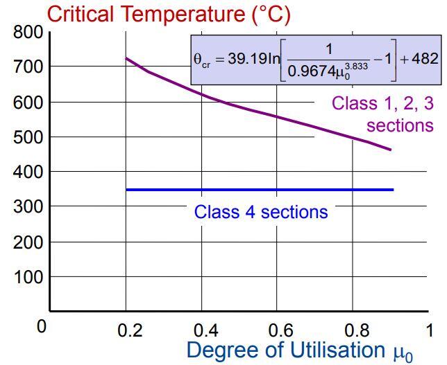
θcr = 39.19In[1/(0.9674μ03.833) – 1] + 482
θcr = 39.19In[1/(0.9674 ×0.4633.833) – 1] + 482 = 596°C
From a more accurate linear interpolation from reduction table (Table 3.1);
ky,θ (0.47) = 600°C
ky,θ (0.463) = ??
ky,θ (0.23) = 700°C
θcr = 600 + (0.463 – 0.47 )/(0.23 – 0.47) × (700 – 600) ≈ 603°C
For the protected section due to protection of the three sides exposed to fire;
κ1 = 0.85 (three sides exposed; insulated)
κ2 = 1.0 (for the unprotected beam having all four sides exposed – clause 4.1(16) of EN 1993-1-2
μ0,m,k = μ0,m(κ1 κ2) = 0.463 × (0.85 × 1.0) = 0.393
The modified degree of utilisation factor for vertical shear
μ0,v,k = μ0,v = 0.166 (no adaptation factor)
μ0 = max (μ0,m,k; μ0,v,k)
μ0 = max (0.393; 0.166) = 0.393
Critical temperature of the protected beam
From equation 4.22 of EN 1993-1-2;
θcr = 39.19In[1/(0.9674μ03.833)- 1] + 482
θcr = 39.19In[1/(0.9674 × 0.3933.833 )- 1] + 482 = 622°C
From a more accurate linear interpolation from reduction table (Table 3.1);
ky,θ (0.47) = 600°C
ky,θ (0.393) = ??
ky,θ (0.23) = 700°C
θcr = 600 + (0.393 – 0.47 )/(0.23 – 0.47) × (700 – 600) ≈ 632°C
Section factor of the unprotected steel beam
Section factor is the ratio of the perimeter of the beam exposed to fire to the volume of the beam section (Am/V). In other words, it is the ratio between “perimeter through which heat is transferred to steel” and “steel volume”.
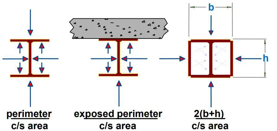
From steel table;
Am/V = 240 m-1 (for UKB 305 x 165 x 40)
(Am/V)b = 185 m-1 (boxed value)
The correction factor for shadow effect;
ksh = 0.9(Am/V)b / (Am/V)
ksh = (0.9 × 185)/240 = 0.6937
Heating of the unprotected beam
The heating of the beam can be obtained from relation 4.25 of EN 1993-1-2.
Δθa.t = (ksh/(ca ρa) × Am/V × hnet,d × Δt —– (1)
We will apply this relationship with the following assumptions;
Δt = time interval increments = 5 seconds
ρa = density of steel = 7850 kg/m3
ca = specific heat of steel = 600 J/kgK
θa.t = 0.6937/(600 × 7850) × 240 × hnet,d × 5
Therefore;
θa.t = (1.7664 × 10⁻⁴)hnet,d
hnet,d (heat flux) has two parts (the convective part hnet,c and the radiative part hnet,r) and varies with time as shown in the equation below. It can be easily calculated if the gas temperature θg is known.
hnet,d = hnet,r + hnet,c
hnet,r = (5.67 × 10⁻⁸)ϕεres [(θg + 273)4 – (θm + 273)4]
hnet,c = αc (θg – θm)
Under standard fire situations;
εres = εf × εm = 0.7 (εf is the emissivity of the fire usually taken as 1.0 while εm is the surface emissivity of the member usually taken as 0.7 for carbon steel)
ϕ (view factor or configuration factor) = 1.0
αc = the coefficient of heat transfer by convection = 25 W/m2K
Therefore;
hnet,r = 3.969 × 10⁻⁸[(θg + 273)4 – (θm + 273)4]
hnet,c = 25(θg – θm)
θg = 20 + 345log(8t + 1) (t in minutes)
θm is the surface temperature of the steel member
The most relevant way to deal with hnet,d is to consider a mean value within the time interval ∆t (5 seconds in this case) between the instant ti and ti+1
hnet,r = 3.969 × 10⁻⁸{[(θg,i + 273)4 + (θg,i+1 + 273)4)]/2- (θa,i + 273)4}
hnet,c = 25[(θg,i + θg,i+1)/2 – θa,i]
When this is solved iteratively, the time at which the bare section reaches critical temperature can be obtained. The temperature development curve can also be plotted. By programming Eq. (1), it is easy to build tables or nomograms like the ones presented in Annex A of Franssen and Real (2015) for unprotected steel profiles subjected to the ISO 834 fire curve. The use of these tables and nomograms avoids the need to solve Eq. (1). The nomograms from Annex A are reproduced in the Figure below.
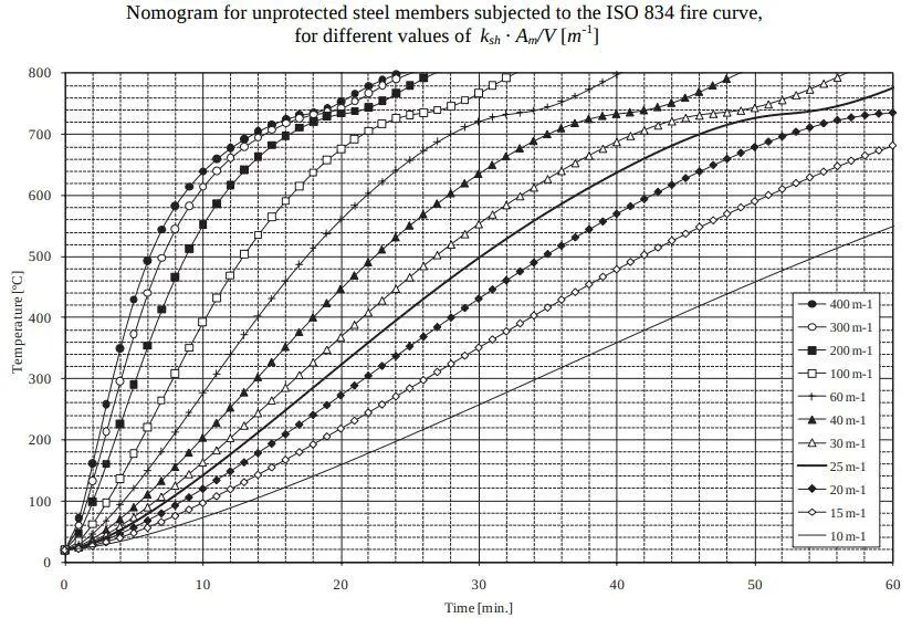
kshAm/V = 166.5 m-1
For a critical temperature of 603°C (for the unprotected beam) and kshAm/V of 166.5 m-1, the time to achieve that temperature when exposed to fire is about 14 minutes. This is less than 30 minutes, therefore the beam cannot be designated as R30.
In the temperature domain;
Table 4.6 gives the temperature after 30 minutes and 60 minutes of standard fire ISO 834 exposure, for different values of the modified section factor ksh[Am/V].
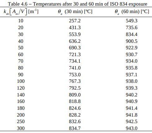
From Table 4.6, the critical temperature for 30 mins for ksh[Am/V] = 166.5 m-1 fire is 825.185°C. Therefore, the temperature in the section exposed on 4 sides after 30 min of standard fire ISO 834 exposure is 825.185°C. As this temperature is greater than the critical temperature, the member doesn’t fulfil the condition for temperature approach verification, because:
θd > θcr,d , at time tfi,requ
This further confirms that the member does not satisfy R30 requirements.









I appreciated it when you shared that structural engineering involved the analysis and designing of slabs, columns, beams, and others for construction projects. It is highly crucial in order to make sure that the building is stable and able to withstand extreme elements. I would like to think if a company needs to find a structural engineering service, it should consider hiring the one that is reputable and experienced.