Beams that have V-shapes (in the plan view) are commonly found in the corners of residential and commercial buildings. According to Hassoun and Al-Manaseer (2008), such beams can be analysed and designed using strain-energy principles especially when the beam is fixed at both ends.
In some scenarios, engineers may be tempted to design v-shaped beams as two cantilevers meeting at a point, but this is not strictly the case. There will be a need to assess other internal stresses such as torsion, and to understand the actual nature of the distribution of internal forces.

For a v-shaped beam subjected to a uniformly distributed load w (kN/m), the internal forces in the members can be obtained as follows;
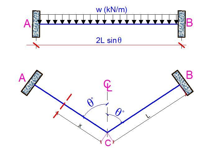
(The bending moment at the centre of the beam Mc is given by;
Mc = (wL2)/6 × [sin2θ/(sin2θ + λcos2θ)
Where;
λ = EI/GJ
L = half the total length of the beam AC
θ = Half the angle between the two sides of the v-shape beam.
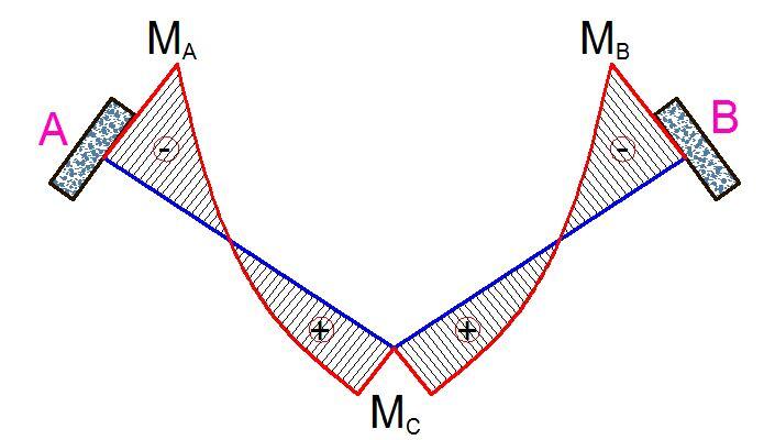
The torsional moment at the centreline of the section is given by;
TC = (MC/sinθ) × cosθ = MCCotθ
At any section N along the length of the beam at a distance x from the centreline C,
MN = MC – wx2/2
TN = TC = MCCotθ (constant torsional moment)
At the supports, let x = L
MA = MC – wL2/2
Worked Example
A v-shaped beam at the corner of a building has a depth of 400mm and a width of 225 mm. The plan view of the beam is shown below. It is to support an ultimate uniformly distributed load of 30 kN/m inclusive of the factored self-weight. Design the beam according to the requirements of EC2. fck = 30 MPa, fyk = 500 MPa, Concrete cover = 35 mm
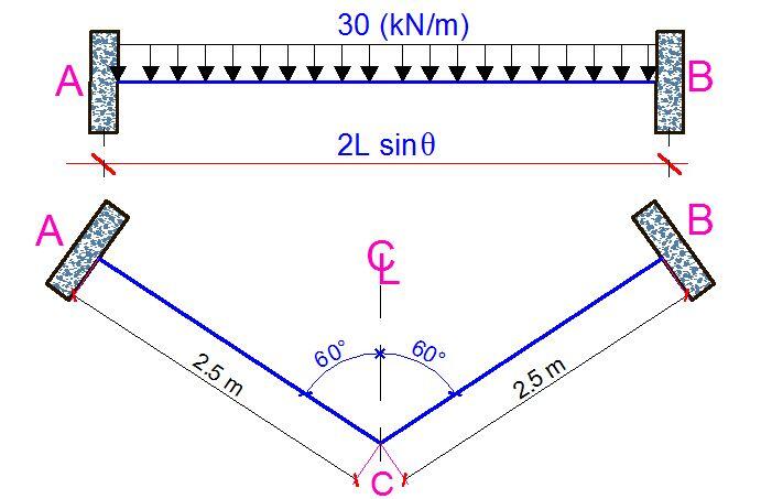
Solution
For fck = 30 MPa,
Modulus of elasticity Ecm = 31476 MPa
Shear modulus G = Ecm/2(1 + v) = 31476/2(1 + 0.2) = 13115 MPa
Moment of inertia I = bd3/12 = (225 × 4003)/12 = 12 × 108 mm4
Polar moment of inertia J = 985033091.649413 mm4
λ = EI/GJ = (31476 × 12 × 108)/(13115 × 985033091.649413) = 2.9237
Mc = [wl2sin2θ/6(sin2θ + λcos2θ) = (30 × 2.52 × 0.75)/[6 × (0.75 + 2.9237 × 0.25)] = 140.625/8.88555 = 15.755 kNm
MA = MB = MC – wl2/2 = 15.755 – (30 x 2.52)/2 = -77.995 kNm
Torsional moment = TA = MCcotθ = 15.755 x 0.5773 = 9.095 kNm
Shear at support = VA = VB = 30 × 2.5 = 75 kN
Let us check these answers using Staad Pro software;
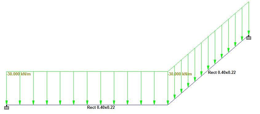
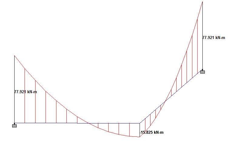

By implication, one can confirm that the analysis method adopted is accurate. The beam can now be designed for torsion, bending, and shear using the guidelines provided in EN 1992-1-1:2004.
References
Hassoun N. M. and Al-Manaseer A. (2008): Structural Concrete Theory and Design. Wiley and Sons Inc, New Jersey, USA



Hi there
Brilliant work.
I have a question about the polar moment of inertia. How was this calculated?
Is it a summation of the moment of inertia’s about both axes?
Many thanks,
Yashiv