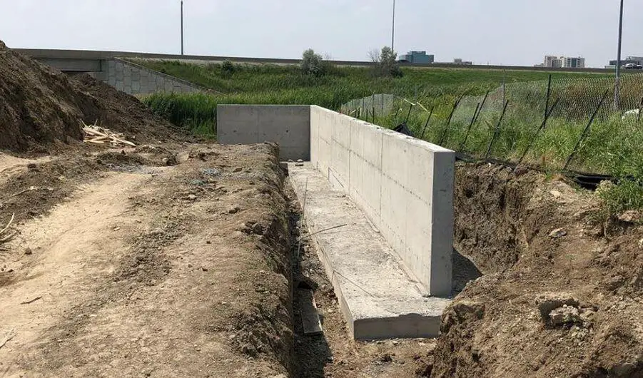
In the design of civil engineering structures, retaining walls are normally used to retain soil (earth materials) and possible hydrostatic pressure, and they are usually found on embankments, highways, basements of buildings, etc. This publication presents an example of the design of cantilever retaining walls.
The fundamental requirement of retaining wall design is that the wall must be able to hold the retained material in place without causing excessive movement due to deflection, overturning, or sliding. Furthermore, the wall must be structurally sound to withstand internal stresses such as bending moment and shear due to the retained soil. This is ensured by providing adequate wall thickness and reinforcement.
Retaining wall design can be separated into three basic phases:
(1) Stability analysis – ultimate limit state (EQU and GEO)
(2) Bearing pressure analysis – ultimate limit state (GEO), and
(3) Member design and detailing – ultimate limit state (STR) and serviceability limit states.
Stability Analysis
A retaining wall must be stable under the action of the loads corresponding to the ultimate limit state (EQU) in terms of resistance to overturning. This is exemplified by the straightforward example of a gravity wall shown below.
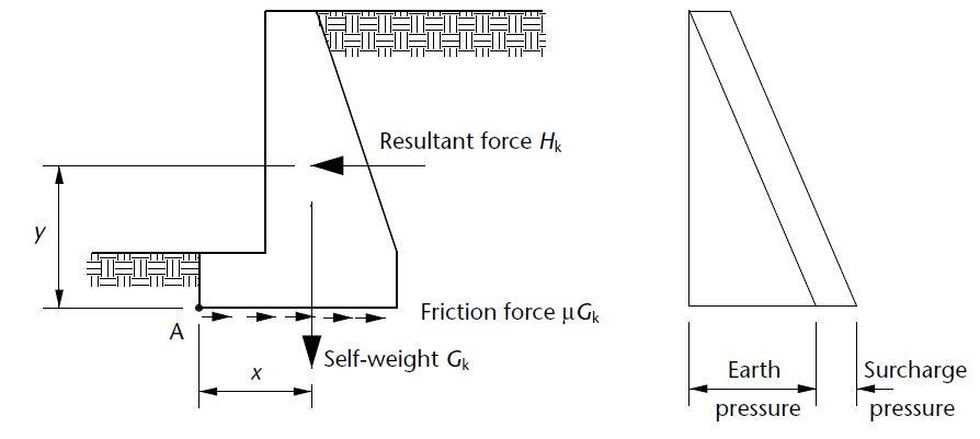
When a maximal horizontal force interacts with a minimal vertical load, overturning becomes critical. It is common practice to apply conservative safety factors of safety to the pressures and weights in order to prevent failure by overturning. The partial factors of safety that are important to these calculations are listed in Table 10.1(c).
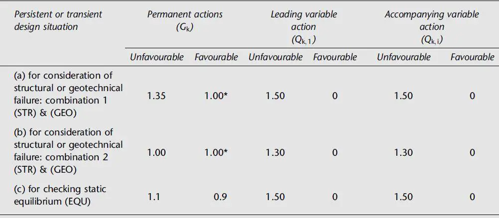
If the permanent load Gk has “favourable” effects, a partial factor of safety of γG = 0.9 is applied, and if the effects of the permanent earth pressure loading at the rear face of the wall have “unfavourable” effects, a partial factor of safety of γf = 1.1 is multiplied. The variable surcharge loading’s “unfavorable” consequences, if any, are compounded by a partial factor of safety of γf = 1.5.
The moment for overturning resistance is normally taken about the toe of the base, at point A on figure 1. Consequently, it is necessary that 0.9Gkx > γfHky.
Friction between the base’s bottom and the ground provides the resistance to sliding, which is why it is also influenced by the entire self-weight Gk. The base’s front face may experience some resistance from passive ground pressure, but as this material is frequently backfilled against the face, this resistance cannot be guaranteed and is typically disregarded.
Failure by sliding is taken into account while analyzing the loads that correspond to the GEO’s final limit condition. The variables that apply to these calculations are listed in the table above. Typically, it is observed that sliding resistance is usually more critical than overturning. If the sliding requirement is not satisfied, a heel beam may be employed, and the force from passive earth pressure across the heel’s face area may be added to the force resisting sliding.
Bearing Pressure Analysis
When evaluating the necessary foundation size, the bearing pressures behind retaining walls are evaluated using the geotechnical ultimate limit state (GEO). The analysis is comparable to what would happen to a foundation if an eccentric vertical load and an overturning moment were to act simultaneously.
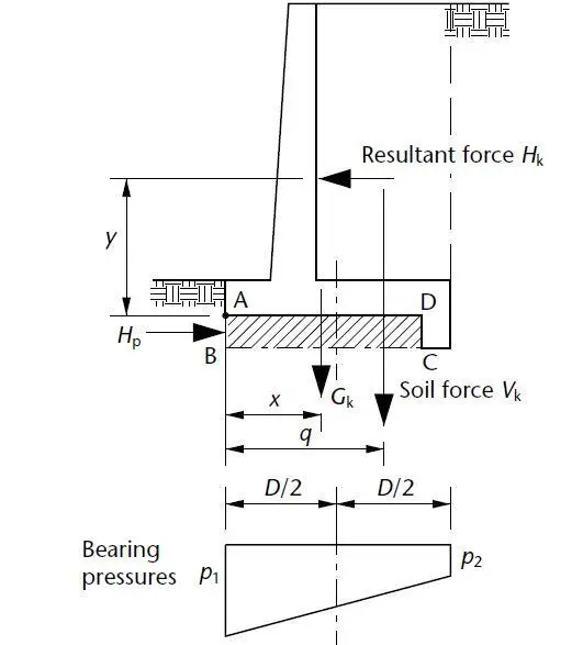
The distribution of bearing pressures will be as shown below, provided the effective eccentricity lies within the ‘middle third’ of the base, that is;
M/P ≤ B/6
Therefore;
pmax = P/B + 6M/B2
pmin = P/B – 6M/B2
In general, section 9 of EN 1997-1 applies to retaining structures supporting ground (i.e. soil, rock or backfill) and/or water and is sub-divided as follows:
§9.1. General
§9.2. Limit states
§9.3. Actions, geometrical data and design situations
§9.4. Design and construction considerations
§9.5. Determination of earth pressures
§9.6. Water pressures
§9.7. Ultimate limit state design
§9.8. Serviceability limit state design
According to EN 1997-1, ultimate limit states GEO and STR must be verified using one of three Design Approaches (DAs). The United Kingdom proposed to adopt Design Approach 1, and this has been used in this design.
The design of gravity walls to Eurocode 7 involves checking that the ground beneath the wall has sufficient:
- bearing resistance to withstand inclined, eccentric actions
- sliding resistance to withstand horizontal and inclined actions
- stability to avoid toppling
- stiffness to prevent unacceptable settlement or tilt
Verification of ultimate limit states (ULSs) is demonstrated by satisfying the inequalities:
Vd ≤ Rd
Hd ≤ Rd
MEd,dst ≤ MEd,stb
In the example downloadable in this post, the retaining wall shown below has been analysed for resistance against sliding, overturning, and bearing. All the calculations were carried out at ultimate limit state.
Member Design and Detailing
The design of bending and shear reinforcement, like that of foundations, is based on a consideration of the loads for the ultimate limit state (STR), along with the accompanying bearing pressures. Steel will rarely be needed in gravity walls, whereas the walls in counterfort and cantilever walls may be designed as slabs. Unless they are quite large, counterforts often have a cantilever beam-like design.
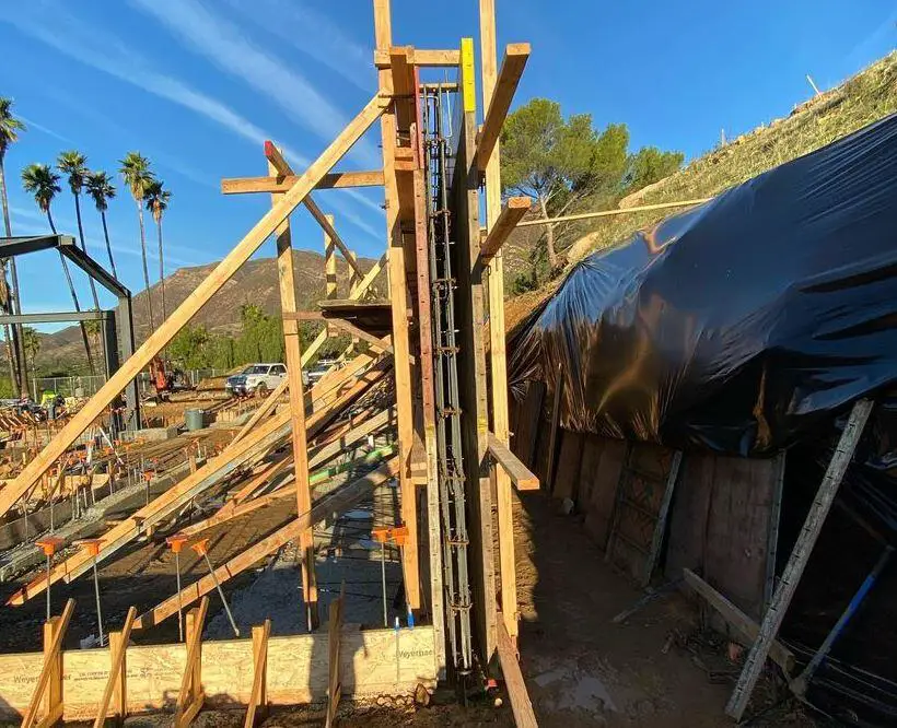
The stem of a retaining wall of the cantilever type is made to resist the moment brought on by the horizontal forces. The thickness of the wall can be calculated as 80mm per metre of backfill for the purposes of preliminary sizing. In most cases, the base’s thickness is the same with the stem’s. The heel and toe need to be made to resist the moments brought on by the downward weight of the base and soil and the upward earth-bearing pressures.
As necessary, reinforcement details of retaining walls must adhere to the general guidelines for slabs and beams. To prevent shrinkage and thermal cracking, special attention must be paid to the reinforcement’s detailing. Because they typically entail enormous concrete pours, gravity walls are particularly prone to damage. Minimal restrictions on thermal and shrinkage movement should be used. The need for strong soil-base friction, however, negates this in the design of bases, making it impossible to create a sliding layer. Therefore, the bases’ reinforcement needs to be sufficient to prevent cracking from being brought on by a lot of constraint.
Due to the loss of hydration heat during thermal movement, long retaining walls supported by inflexible bases are especially prone to cracking, thus detailing must make an effort to disperse the cracks to maintain appropriate widths. There must be full vertical movement joints available. Waterbars and sealants should be used, and these joints frequently include a shear key to stop differential movement of adjacent wall sections.
Groundwater hydrostatic forces are typically applied to the back sides of retaining walls. By including a drainage passage at the face of the wall, these might be decreased. A layer of earth or porous blocks with pipes to remove the water, frequently through the front of the wall, is the customary method for creating such a drain. Water is less likely to flow through the retaining wall, cause damage to the soil beneath the wall’s foundations, and cause hydrostatic pressure on the wall to decrease as a result.
Retaining Wall Analysis and Design Example
A cantilever retaining wall is loaded as shown below. Design the retaining wall in accordance with EN1997-1:2004 incorporating Corrigendum dated February 2009 and the UK National Annex incorporating Corrigendum No.1.
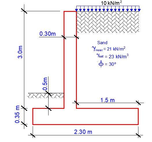
Retaining wall details
Stem type; Cantilever
Stem height; hstem = 3000 mm
Stem thickness; tstem = 300 mm
Angle to rear face of stem; α = 90 deg
Stem density; γstem = 25 kN/m3
Toe length; ltoe = 500 mm
Heel length; lheel = 1500 mm
Base thickness; tbase = 350 mm
Base density; γbase = 25 kN/m3
Height of retained soil; hret = 2500 mm
Angle of soil surface; β = 0 deg
Depth of cover; dcover = 500 mm
Depth of excavation; dexc = 200 mm
Retained soil properties
Soil type; Medium-dense well graded sand
Moist density; γmr = 21 kN/m3
Saturated density; γsr = 23 kN/m3
Characteristic effective shear resistance angle; φ’r.k = 30 deg
Characteristic wall friction angle; δr.k = 0 deg
Base soil properties
Soil type; Medium-dense well graded sand
Soil density; γb = 18 kN/m3
Characteristic cohesion; c’b.k = 0 kN/m2
Characteristic effective shear resistance angle; φ’b.k = 30 deg
Characteristic wall friction angle; δb.k = 15 deg
Characteristic base friction angle; δbb.k = 30 deg
Loading details
Variable surcharge load; SurchargeQ = 10 kN/m2
Retaining wall geometry
Base length; lbase = ltoe + tstem + lheel = 2300 mm
Moist soil height; hmoist = hsoil = 3000 mm
Length of surcharge load; lsur = lheel = 1500 mm
– Distance to vertical component; xsur_v = lbase – (lheel / 2) = 1550 mm
Effective height of wall; heff = hbase + dcover + hret = 3350 mm
– Distance to horizontal component; xsur_h = heff / 2 = 1675 mm
Area of wall stem; Astem = hstem × tstem = 0.9 m2
– Distance to vertical component; xstem = ltoe + tstem / 2 = 650 mm
Area of wall base; Abase = lbase × tbase = 0.805 m2
– Distance to vertical component; xbase = lbase / 2 = 1150 mm
Area of moist soil; Amoist = hmoist × lheel = 4.5 m2
– Distance to vertical component; xmoist_v = lbase – (hmoist × lheel2 / 2) / Amoist = 1550 mm
– Distance to horizontal component; xmoist_h = heff / 3 = 1117 mm
Area of base soil; Apass = dcover × ltoe = 0.25 m2
– Distance to vertical component; xpass_v = lbase – [dcover × ltoe × (lbase – ltoe/2)] / Apass = 250 mm
– Distance to horizontal component; xpass_h = (dcover + hbase) / 3 = 283 mm
Area of excavated base soil; Aexc = hpass × ltoe = 0.15 m2
– Distance to vertical component; xexc_v = lbase – [hpass × ltoe × (lbase – ltoe/2)] / Aexc = 250 mm
– Distance to horizontal component; xexc_h = (hpass + hbase) / 3 = 217 mm
Design approach 1 – Combination 1
Partial factor set; A1
Permanent unfavourable action; γG = 1.35
Permanent favourable action; γGf = 1.00
Variable unfavourable action; γQ = 1.50
Variable favourable action; γQf = 0.00
Partial factors for soil parameters – Table A.4 – Combination 1
Soil parameter set; M1
Angle of shearing resistance; γφ‘ = 1.00
Effective cohesion; γc’ = 1.00
Weight density; γg = 1.00
Retained soil properties
Design moist density; γmr‘ = γmr / γg = 21 kN/m3
Design saturated density; γsr‘ = γsr / γg = 23 kN/m3
Design effective shear resistance angle; φ’r.d = tan-1(tan(φ’r.k) / γφ’) = 30 deg
Design wall friction angle; δr.d = tan-1(tan(δr.k) / γφ’) = 0 deg
Base soil properties
Design soil density; γb‘ = γb/γg = 18 kN/m3
Design effective shear resistance angle; φ’b.d = tan-1(tan(φ’b.k) / γφ’) = 30 deg
Design wall friction angle; δb.d = tan-1(tan(δb.k) / γφ’) = 15 deg
Design base friction angle; δbb.d = tan-1(tan(δbb.k) / γφ’) = 30 deg
Design effective cohesion; c’b.d = c’b.k / γc’ = 0 kN/m2
Using Rankine theory
Active pressure coefficient; KA = (1 – sin(φ’r.d)) / (1 + sin(φ’r.d)) = 0.333
Passive pressure coefficient; KP = (1 + sin(φ’b.d)) / (1 – sin(φ’b.d)) = 3.000
Sliding check
Vertical forces on wall
Wall stem; Fstem = γGf × Astem × γstem = 22.5 kN/m
Wall base; Fbase = γGf × Abase × γbase = 20.1 kN/m
Moist retained soil; Fmoist_v = γGf × Amoist × γmr‘ = 94.5 kN/m
Base soil; Fexc_v = γGf × Aexc × γb‘ = 2.7 kN/m
Total; Ftotal_v = Fstem + Fbase + Fmoist_v + Fexc_v = 139.8 kN/m
Horizontal forces on wall
Surcharge load; Fsur_h = KA × γQ × SurchargeQ × heff = 16.8 kN/m
Moist retained soil;Fmoist_h = γG × KA × γmr‘ × heff2 / 2 = 53 kN/m
Total; Ftotal_h = Fsur_h + Fmoist_h = 69.8 kN/m
Check stability against sliding
Base soil resistance; Fexc_h = γGfKPγb‘ × (hpass + hbase)2 / 2 = 11.4 kN/m
Base friction; Ffriction = Ftotal_v × tan(δbb.d) = 80.7 kN/m
Resistance to sliding; Frest = Fexc_h + Ffriction = 92.1 kN/m
Factor of safety; FoSsl = Frest / Ftotal_h = 1.32
PASS – Resistance to sliding is greater than sliding force
Overturning check
Vertical forces on wall
Wall stem; Fstem = γGf × Astem × γstem = 22.5 kN/m
Wall base; Fbase = γGf × Abase × γbase = 20.1 kN/m
Moist retained soil; Fmoist_v = γGf × Amoist × γmr‘ = 94.5 kN/m
Base soil; Fexc_v = γGf × Aexc × γb‘ = 2.7 kN/m
Total; Ftotal_v = Fstem + Fbase + Fmoist_v + Fexc_v = 139.8 kN/m
Horizontal forces on wall
Surcharge load; Fsur_h = KA × γQ × SurchargeQ × heff = 16.8 kN/m
Moist retained soil; Fmoist_h = γG × KA × γmr‘ × heff2 / 2 = 53 kN/m
Base soil; Fexc_h = -γGf × KP × γb‘ × (hpass + hbase)2 / 2 = -11.4 kN/m
Total; Ftotal_h = Fsur_h + Fmoist_h + Fexc_h = 58.4 kN/m
Overturning moments on wall
Surcharge load; Msur_OT = Fsur_h × xsur_h = 28.1 kNm/m
Moist retained soil; Mmoist_OT = Fmoist_h × xmoist_h = 59.2 kNm/m
Total; Mtotal_OT = Msur_OT + Mmoist_OT = 87.3 kNm/m
Restoring moments on wall
Wall stem; Mstem_R = Fstem × xstem = 14.6 kNm/m
Wall base; Mbase_R = Fbase × xbase = 23.1 kNm/m
Moist retained soil; Mmoist_R = Fmoist_v × xmoist_v = 146.5 kNm/m
Base soil; Mexc_R = Fexc_v × xexc_v – Fexc_h × xexc_h = 3.1 kNm/m
Total; Mtotal_R = Mstem_R + Mbase_R + Mmoist_R + Mexc_R = 187.4 kNm/m
Check stability against overturning
Factor of safety; FoSot = Mtotal_R / Mtotal_OT = 2.147
PASS – Maximum restoring moment is greater than the overturning moment
Bearing pressure check
Vertical forces on wall
Wall stem; Fstem = γG × Astem × γstem = 30.4 kN/m
Wall base; Fbase = γG × Abase × γbase = 27.2 kN/m
Surcharge load; Fsur_v = γQ × SurchargeQ × lheel = 22.5 kN/m
Moist retained soil; Fmoist_v = γG × Amoist × γmr‘ = 127.6 kN/m
Base soil; Fpass_v = γG × Apass × γb‘ = 6.1 kN/m
Total; Ftotal_v = Fstem + Fbase + Fsur_v + Fmoist_v + Fpass_v = 213.7 kN/m
Horizontal forces on wall
Surcharge load; Fsur_h = KA × γQ × SurchargeQ × heff = 16.8 kN/m
Moist retained soil; Fmoist_h = γG × KA × γmr‘ × heff2 / 2 = 53 kN/m
Base soil; Fpass_h = -γGf × KP × γb‘ × (dcover + hbase)2 / 2 = -19.5 kN/m
Total; Ftotal_h = max(Fsur_h + Fmoist_h + Fpass_h – Ftotal_v × tan(dbb.d), 0 kN/m) = 0 kN/m
Moments on wall
Wall stem; Mstem = Fstem × xstem = 19.7 kNm/m
Wall base; Mbase = Fbase × xbase = 31.2 kNm/m
Surcharge load; Msur = Fsur_v × xsur_v – Fsur_h × xsur_h = 6.8 kNm/m
Moist retained soil; Mmoist = Fmoist_v × xmoist_v – Fmoist_h × xmoist_h = 138.5 kNm/m
Base soil; Mpass = Fpass_v × xpass_v – Fpass_h × xpass_h = 7 kNm/m
Total; Mtotal = Mstem + Mbase + Msur + Mmoist + Mpass = 203.4 kNm/m
Check bearing pressure
Distance to reaction; x’ = Mtotal / Ftotal_v = 952 mm
Eccentricity of reaction; e = x’ – lbase / 2 = -198 mm
Loaded length of base; lload = 2x’ = 1903 mm
Bearing pressure at toe; qtoe = Ftotal_v / lload = 112.3 kN/m2
Bearing pressure at heel; qheel = 0 kN/m2
Effective overburden pressure; q = (tbase + dcover)γb‘ = 15.3 kN/m2
Design effective overburden pressure; q’ = q / γg = 15.3 kN/m2
Bearing resistance factors;
Nq = Exp(π × tan(φ’b.d)) × (tan(45 deg + φ’b.d / 2))2 = 18.401
Nc = (Nq – 1)cot(φ’b.d) = 30.14
Nγ = 2(Nq – 1)tan(φ’b.d) = 20.093
Foundation shape factors;
sq = 1
sγ = 1
sc = 1
Load inclination factors;
H = Fsur_h + Fmoist_h + Fpass_h = 50.3 kN/m
V = Ftotal_v = 213.7 kN/m
m = 2
iq = [1 – H / (V + lload × c’b.d × cot(φ’b.d))]m = 0.585
iγ = [1 – H / (V + lload × c’b.d × cot(φ’b.d))](m + 1) = 0.447
ic = iq – (1 – iq) / (Nc × tan(φ’b.d)) = 0.561
Net ultimate bearing capacity
nf = c’b.dNcscic + q’Nqsqiq + 0.5γb‘lloadNγsγiγ = 318.6 kN/m2
Factor of safety;
FoSbp = nf / max(qtoe, qheel) = 2.838
PASS – Allowable bearing pressure exceeds maximum applied bearing pressure
Design approach 1 – Combination 2
Partial factor set; A2
Permanent unfavourable action; γG = 1.00
Permanent favourable action; γGf = 1.00
Variable unfavourable action; γQ = 1.30
Variable favourable action; γQf = 0.00
Soil parameter set; M2
Angle of shearing resistance; γf’ = 1.25
Effective cohesion; γc’ = 1.25
Weight density; γg = 1.00
Retained soil properties
Design moist density; γmr‘ = γmr/γg = 21 kN/m3
Design saturated density; γsr‘ = γsr/γg = 23 kN/m3
Design effective shear resistance angle; φ’r.d = tan-1(tan(φ’r.k) / γφ’) = 24.8 deg
Design wall friction angle; δr.d = tan-1(tan(δr.k) / γφ’) = 0 deg
Base soil properties
Design soil density; γb‘ = γb/γg = 18 kN/m3
Design effective shear resistance angle; φ’b.d = tan-1(tan(φ’b.k) / γφ’) = 24.8 deg
Design wall friction angle; δb.d = tan-1(tan(δb.k) / γφ’) = 12.1 deg
Design base friction angle; δbb.d = tan-1(tan(δbb.k) / γφ’) = 24.8 deg
Design effective cohesion; c’b.d = c’b.k /γc’ = 0 kN/m2
Using Rankine theory
Active pressure coefficient;
KA = (1 – sin(φ’r.d)) / (1 + sin(φ’r.d)) = 0.409
Passive pressure coefficient;
KP = (1 + sin(φ’b.d)) / (1 – sin(φ’b.d)) = 2.444
Sliding check
Vertical forces on wall
Wall stem; Fstem = γGf × Astem × γstem = 22.5 kN/m
Wall base; Fbase = γGf × Abase × γbase = 20.1 kN/m
Moist retained soil;Fmoist_v = γGf × Amoist × γmr‘ = 94.5 kN/m
Base soil;Fexc_v = γGf × Aexc × γb‘ = 2.7 kN/m
Total; Ftotal_v = Fstem + Fbase + Fmoist_v + Fexc_v = 139.8 kN/m
Horizontal forces on wall
Surcharge load; Fsur_h = KA × γQ × SurchargeQ × heff = 17.8 kN/m
Moist retained soil; Fmoist_h = γG × KA × γmr‘ × heff2 / 2 = 48.2 kN/m
Total; Ftotal_h = Fsur_h + Fmoist_h = 66 kN/m
Check stability against sliding
Base soil resistance; Fexc_h = γGf × KP × γb‘ × (hpass + hbase)2 / 2 = 9.3 kN/m
Base friction; Ffriction = Ftotal_v × tan(dbb.d) = 64.6 kN/m
Resistance to sliding; Frest = Fexc_h + Ffriction = 73.9 kN/m
Factor of safety; FoSsl = Frest / Ftotal_h = 1.119
PASS – Resistance to sliding is greater than sliding force
Overturning check
Vertical forces on wall
Wall stem; Fstem = γGf × Astem × γstem = 22.5 kN/m
Wall base; Fbase = γGf × Abase × γbase = 20.1 kN/m
Moist retained soil; Fmoist_v = γGf × Amoist × γmr‘ = 94.5 kN/m
Base soil; Fexc_v = γGf × Aexc × γb‘ = 2.7 kN/m
Total; Ftotal_v = Fstem + Fbase + Fmoist_v + Fexc_v = 139.8 kN/m
Horizontal forces on wall
Surcharge load; Fsur_h = KA × γQ × SurchargeQ × heff = 17.8 kN/m
Moist retained soil; Fmoist_h = γG × KA × γmr‘ × heff2 / 2 = 48.2 kN/m
Base soil; Fexc_h = -γGf × KP × γb‘ × (hpass + hbase)2 / 2 = -9.3 kN/m
Total; Ftotal_h = Fsur_h + Fmoist_h + Fexc_h = 56.7 kN/m
Overturning moments on wall
Surcharge load; Msur_OT = Fsur_h × xsur_h = 29.8 kNm/m
Moist retained soil; Mmoist_OT = Fmoist_h × xmoist_h = 53.8 kNm/m
Total; Mtotal_OT = Msur_OT + Mmoist_OT = 83.7 kNm/m
Restoring moments on wall
Wall stem; Mstem_R = Fstem × xstem = 14.6 kNm/m
Wall base; Mbase_R = Fbase × xbase = 23.1 kNm/m
Moist retained soil; Mmoist_R = Fmoist_v × xmoist_v = 146.5 kNm/m
Base soil; Mexc_R = Fexc_v × xexc_v – Fexc_h × xexc_h = 2.7 kNm/m
Total; Mtotal_R = Mstem_R + Mbase_R + Mmoist_R + Mexc_R = 186.9 kNm/m
Check stability against overturning
Factor of safety; FoSot = Mtotal_R / Mtotal_OT = 2.234
PASS – Maximum restoring moment is greater than overturning moment
Bearing pressure check
Vertical forces on wall
Wall stem; Fstem = γG × Astem × γstem = 22.5 kN/m
Wall base; Fbase = γG × Abase × γbase = 20.1 kN/m
Surcharge load; Fsur_v = γQ × SurchargeQ × lheel = 19.5 kN/m
Moist retained soil; Fmoist_v = γG × Amoist × γmr‘ = 94.5 kN/m
Base soil; Fpass_v = γG × Apass × γb‘ = 4.5 kN/m
Total; Ftotal_v = Fstem + Fbase + Fsur_v + Fmoist_v + Fpass_v = 161.1 kN/m
Horizontal forces on wall
Surcharge load; Fsur_h = KA × γQ × SurchargeQ × heff = 17.8 kN/m
Moist retained soil; Fmoist_h = γG × KA × γmr‘ × heff2 / 2 = 48.2 kN/m
Base soil; Fpass_h = -γGf × KP × γb‘ × (dcover + hbase)2 / 2 = -15.9 kN/m
Total; Ftotal_h = max(Fsur_h + Fmoist_h + Fpass_h – Ftotal_v × tan(δbb.d), 0 kN/m) = 0 kN/m
Moments on wall
Wall stem; Mstem = Fstem × xstem = 14.6 kNm/m
Wall base; Mbase = Fbase × xbase = 23.1 kNm/m
Surcharge load; Msur = Fsur_v × xsur_v – Fsur_h × xsur_h = 0.4 kNm/m
Moist retained soil; Mmoist = Fmoist_v × xmoist_v – Fmoist_h × xmoist_h = 92.6 kNm/m
Base soil; Mpass = Fpass_v × xpass_v – Fpass_h × xpass_h = 5.6 kNm/m
Total; Mtotal = Mstem + Mbase + Msur + Mmoist + Mpass = 136.4 kNm/m
Check bearing pressure
Distance to reaction; x’ = Mtotal / Ftotal_v = 847 mm
Eccentricity of reaction; e = x’ – lbase / 2 = -303 mm
Loaded length of base; lload = 2x’ = 1693 mm
Bearing pressure at toe; qtoe = Ftotal_v / lload = 95.2 kN/m2
Bearing pressure at heel; qheel = 0 kN/m2
Effective overburden pressure; q = (tbase + dcover)γb‘ = 15.3 kN/m2
Design effective overburden pressure; q’ = q/γg = 15.3 kN/m2
Bearing resistance factors;
Nq = Exp[πtan(φ’b.d)] × [tan(45 deg + φ’b.d / 2)]2 = 10.431
Nc = (Nq – 1) × cot(φ’b.d) = 20.418
Nγ = 2(Nq – 1) × tan(φ’b.d) = 8.712
Foundation shape factors;
sq = 1
sγ = 1
sc = 1
Load inclination factors;
H = Fsur_h + Fmoist_h + Fpass_h = 50.1 kN/m
V = Ftotal_v = 161.1 kN/m
m = 2
iq = [1 – H / (V + lload × c’b.d × cot(φ’b.d))]m = 0.475
iγ = [1 – H / (V + lload × c’b.d × cot(f’φb.d))](m + 1) = 0.327
ic = iq – (1 – iq) / (Nc × tan(φ’b.d)) = 0.419
Net ultimate bearing capacity
nf = c’b.dNcscic + q’Nqsqiq + 0.5γb‘lload Nγsγiγ = 119.1 kN/m2
Library item: Drained bearing output
Factor of safety;
FoSbp = nf / max(qtoe, qheel) = 1.252
PASS – Allowable bearing pressure exceeds maximum applied bearing pressure
Analysis summary
| Description | Unit | Capacity | Applied | F o S | Result |
| Sliding stability | kN/m | 73.9 | 66 | 1.119 | PASS |
| Overturning stability | kNm/m | 187.4 | 87.3 | 2.147 | PASS |
| Bearing pressure | kN/m2 | 119.1 | 95.2 | 1.252 | PASS |
Structural Design
In accordance with EN1992-1-1:2004 incorporating Corrigendum dated January 2008 and the UK National Annex incorporating National Amendment No.1
Concrete details
Concrete strength class; C20/25
Characteristic compressive cylinder strength; fck = 20 N/mm2
Characteristic compressive cube strength; fck,cube = 25 N/mm2
Mean value of compressive cylinder strength; fcm = fck + 8 N/mm2 = 28 N/mm2
Mean value of axial tensile strength; fctm = 0.3(fck)2/3 = 2.2 N/mm2
5% fractile of axial tensile strength; fctk,0.05 = 0.7fctm = 1.5 N/mm2
Secant modulus of elasticity of concrete; Ecm = 22 kN/mm2(fcm/10)0.3 = 29962 N/mm2
Partial factor for concrete – Table 2.1N; γC = 1.50
Compressive strength coefficient – cl.3.1.6(1); acc = 0.85
Design compressive concrete strength – exp.3.15; fcd = acc(fck/γC) = 11.3 N/mm2
Maximum aggregate size; hagg = 20 mm
Ultimate strain – Table 3.1; εcu2 = 0.0035
Shortening strain – Table 3.1; εcu3 = 0.0035
Effective compression zone height factor; λ = 0.80
Effective strength factor; h = 1.00
Bending coefficient k1; K1 = 0.40
Bending coefficient k2; K2 = 1.00(0.6 + 0.0014/εcu2) = 1.00
Bending coefficient k3; K3 =0.40
Bending coefficient k4; K4 = 1.00(0.6 + 0.0014/εcu2) =1.00
Reinforcement details
Characteristic yield strength of reinforcement; fyk = 500 N/mm2
Modulus of elasticity of reinforcement; Es = 200000 N/mm2
Partial factor for reinforcing steel – Table 2.1N; γS = 1.15
Design yield strength of reinforcement; fyd = fyk / γS = 435 N/mm2
Cover to reinforcement
Front face of stem; csf = 40 mm
Rear face of stem; csr = 50 mm
Top face of base; cbt = 50 mm
Bottom face of base; cbb = 75 mm
Check stem design at base of stem
Depth of section; h = 300 mm
Flexural Design (Bending)
Design bending moment combination 1;
M = 65 kNm/m
d = h – csr – φsr / 2 = 244 mm
K = M / (d2fck) = 0.055
K’ = (2h acc/γC) × [1 – λ(d – K1)/(2K2)] × [λ(d – K1)/(2K2)]
K’ = 0.207
K’ > K – No compression reinforcement is required
Lever arm; z = min(0.5 + 0.5(1 – 2K / (h × acc / γC))0.5, 0.95)d = 232 mm
Depth of neutral axis; x = 2.5(d – z) = 31 mm
Area of tension reinforcement required; Asr.req = M / (fydz) = 646 mm2/m
Tension reinforcement provided; 12 dia.bars @ 150 c/c ( Asr.prov = 754 mm2/m)
Minimum area of reinforcement – exp.9.1N; Asr.min = max(0.26fctm / fyk, 0.0013)d = 317 mm2/m
Maximum area of reinforcement – cl.9.2.1.1(3);Asr.max = 0.04h = 12000 mm2/m
max(Asr.req, Asr.min) / Asr.prov = 0.856
PASS – Area of reinforcement provided is greater than area of reinforcement required
Deflection control
Reference reinforcement ratio; ρ0 = √(fck) / 1000 = 0.004
Required tension reinforcement ratio; ρ = Asr.req / d = 0.003
Required compression reinforcement ratio; ρ’ = Asr.2.req / d2 = 0.000
Structural system factor – Table 7.4N; Kb = 0.4
Reinforcement factor – exp.7.17; Ks = min(500 / (fykAsr.req / Asr.prov), 1.5) = 1.168
Limiting span to depth ratio – exp.7.16.a;
min(KsKb[11 + 1.5 × √(fck) ρ0/ρ + 3.2√(fck) × (ρ0/ρ – 1)3/2], 40Kb) = 14.3
Actual span to depth ratio; hstem / d = 12.3
PASS – Span to depth ratio is less than deflection control limit
Rectangular section in shear
Design shear force; V = 57.5 kN/m
CRd,c = 0.18 / γC = 0.120
k = min(1 + √(200 mm / d), 2) = 1.905
Longitudinal reinforcement ratio; ρl = min(Asr.prov / d, 0.02) = 0.003
vmin = 0.035k3/2fck0.5 = 0.412 N/mm2
Design shear resistance – exp.6.2a & 6.2b;
VRd.c = max(CRd.ck(100ρlfck)1/3, vmin)d
VRd.c = 102.4 kN/m
V / VRd.c = 0.562
PASS – Design shear resistance exceeds design shear force
Horizontal reinforcement parallel to face of stem – Section 9.6
Minimum area of reinforcement – cl.9.6.3(1);
Asx.req = max(0.25Asr.prov, 0.001tstem) = 300 mm2/m
Maximum spacing of reinforcement – cl.9.6.3(2); ssx_max = 400 mm
Transverse reinforcement provided; H10 dia.bars @ 200 c/c (Asx.prov = 393 mm2/m)
PASS – Area of reinforcement provided is greater than area of reinforcement required
Check base design at toe
Depth of section; h = 350 mm
Rectangular section in flexure
Design bending moment combination 1;
M = 13.8 kNm/m
d = h – cbb – φbb / 2 = 269 mm
K = M / (d2 fck) = 0.010
K’ = (2h × acc/γC) × (1 – λ(d – K1)/(2K2)) × (λ(d – K1)/(2K2))
K’ = 0.207
K’ > K – No compression reinforcement is required
Lever arm;
z = min(0.5 + 0.5(1 – 2K / (h × acc/γC))0.5, 0.95)d = 256 mm
Depth of neutral axis; x = 2.5(d – z) = 34 mm
Area of tension reinforcement required; Abb.req = M / (fydz) = 124 mm2/m
Tension reinforcement provided;
12 dia.bars @ 200 c/c ( Abb.prov = 565 mm2/m)
Minimum area of reinforcement – exp.9.1N;
Abb.min = max(0.26fctm/fyk, 0.0013)d = 350 mm2/m
Maximum area of reinforcement – cl.9.2.1.1(3);
Abb.max = 0.04h = 14000 mm2/m
max(Abb.req, Abb.min) / Abb.prov = 0.618
PASS – Area of reinforcement provided is greater than area of reinforcement required
Rectangular section in shear
Design shear force;
V = 53.3 kN/m
CRd,c = 0.18/γC = 0.120
k = min(1 + √(200 mm / d), 2) = 1.862
Longitudinal reinforcement ratio; ρl = min(Abb.prov / d, 0.02) = 0.002
vmin = 0.035 k3/2fck0.5 = 0.398 N/mm2
Design shear resistance – exp.6.2a & 6.2b;
VRd.c = max(CRd.ck(100ρlfck)1/3, vmin) d
VRd.c = 107 kN/m
V / VRd.c = 0.498
PASS – Design shear resistance exceeds design shear force
Check base design at heel
Depth of section; h = 350 mm
Rectangular section in flexure
Design bending moment combination 1;
M = 51.9 kNm/m
d = h – cbt – φbt / 2 = 294 mm
K = M / (d2fck) = 0.030
K’ = (2h × αcc/γC) × (1 – λ(d – K1)/(2K2)) × (λ(d – K1)/(2K2))
K’ = 0.207
K’ > K – No compression reinforcement is required
Lever arm; z = min(0.5 + 0.5(1 – 2K/(h × αcc/γC))0.5, 0.95)d = 279 mm
Depth of neutral axis; x = 2.5(d – z) = 37 mm
Area of tension reinforcement required;
Abt.req = M / (fydz) = 427 mm2/m
Tension reinforcement provided;
12 dia.bars @ 200 c/c (Abt.prov = 565 mm2/m)
Minimum area of reinforcement – exp.9.1N;
Abt.min = max(0.26fctm/fyk, 0.0013)d = 382 mm2/m
Maximum area of reinforcement – cl.9.2.1.1(3);
Abt.max = 0.04h = 14000 mm2/m
max(Abt.req, Abt.min) / Abt.prov = 0.755
PASS – Area of reinforcement provided is greater than area of reinforcement required
Rectangular section in shear
Design shear force;
V = 53.5 kN/m
CRd,c = 0.18 / γC = 0.120
k = min(1 + √(200 mm / d), 2) = 1.825
Longitudinal reinforcement ratio;
ρl = min(Abt.prov / d, 0.02) = 0.002
vmin = 0.035k3/2fck0.5 = 0.386 N/mm2
Design shear resistance – exp.6.2a & 6.2b;
VRd.c = max(CRd.ck (100 ρlfck)1/3, vmin)d
VRd.c = 113.4 kN/m
V / VRd.c = 0.472
PASS – Design shear resistance exceeds design shear force
Secondary transverse reinforcement to base – Section 9.3
Minimum area of reinforcement – cl.9.3.1.1(2);
Abx.req = 0.2Abb.prov = 113 mm2/m
Maximum spacing of reinforcement – cl.9.3.1.1(3);
sbx_max = 450 mm
Transverse reinforcement provided;
10 dia.bars @ 200 c/c (Abx.prov = 393 mm2/m)
PASS – Area of reinforcement provided is greater than area of reinforcement required
Summary
| Description | Unit | Provided | Required | Utilisation | Result |
| Stem ρ0 rear face – Flexural reinforcement | mm2/m | 754.0 | 645.7 | 0.86 | PASS |
| Stem ρ0 – Shear resistance | kN/m | 102.4 | 57.5 | 0.56 | PASS |
| Base top face – Flexural reinforcement | mm2/m | 565.5 | 427.2 | 0.76 | PASS |
| Base bottom face – Flexural reinforcement | mm2/m | 565.5 | 349.7 | 0.62 | PASS |
| Base – Shear resistance | kN/m | 107.0 | 53.3 | 0.50 | PASS |
| Transverse stem reinforcement | mm2/m | 392.7 | 300.0 | 0.76 | PASS |
| Transverse base reinforcement | mm2/m | 392.7 | 113.1 | 0.29 | PASS |





Thanks for clear calculation. Good job.
Hi,
Where does the M value come from in the Design bending moment combination 1 for the check stem design at base of stem.
Any help would be appreciated.
Mikolaj
Thank you for the clear explanation of structural wall design basics! Which failure mode: sliding, overturning, or bearing, is most common in residential projects?