A lot of correlations have been proposed by researchers for relating the results from Standard Penetration Test (SPT) and Cone Penetration Test (CPT) to pile load capacity. In this article, we are going to review how to design pile foundation using SPT and CPT data. It very important that these correlations used in this article and other similar ones should be used with caution, since they are statistical relationships that may not have taken all parameters into consideration. Experience is required to successful apply them to practice.
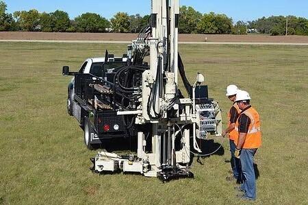
It is common to use the results of in-situ tests to determine the ultimate bearing capacity of piles in coarse soils because it is difficult to get undisturbed samples of these soils from boreholes. Two fundamental approaches will be discussed in this article, which are SPT and CPT.
In all cases, the allowable load is calculated by dividing the ultimate bearing capacity by a safety factor which usually varies between 2 and 3. The diameter of the pile and the soil’s compressibility both have an impact on the allowable settlement at the working load. Experience has shown that a safety factor of 2.5 will guarantee that an isolated pile driven into coarse soil with a shaft diameter of no more than 600 mm won’t settle by more than 15 mm.
As an alternative, partial safety factors can be used in accordance with the steps outlined in EC7, and the serviceability limit state can be verified through calculation or experience, and if necessary, by performing loading tests. If the “global” safety factor of 2.5 is utilised, these tests are still required unless experience offers a more reliable indicator of settlement behaviour.
Standard Penetration Test (SPT)
For driven piles in coarse-grained soils (sands), Meyerhof (1956) proposed the following relationship between the skin friction (fs) of the pile and the standard penetration number;
Skin friction
The skin friction in piles can be obtained from SPT data using the relationships in Equations (1-3);
Qf = fs × perimeter × length ——– (1)
For Displacement piles: fs = 1.9N60; fs ≤ 100 kPa ——– (2)
For Non-displacement piles: fs = 0.95N60; fs ≤ 50 kPa ——– (3)
End bearing
The end bearing in piles can be obtained from SPT data using the relationships in Equations (4-6);
Qb = fbAb ——– (4)
fb = CN60 (kPa) ——– (5)
C = 38(Ls/D) ≤ 380 ——– (6)
where Ls is the length of pile driven in sand, and D is the diameter of the pile.
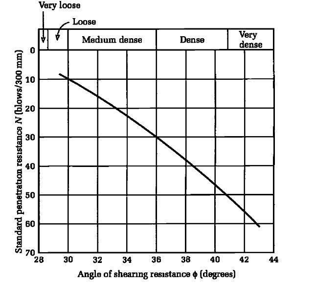
Alternatively, the standard penetration number can be used to estimate the angle of internal friction of the soil (using Figure 2), which is then used to compute the allowable load on the pile.
Cone Penetration Test (CPT)
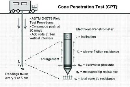
The cone penetrometer was originally developed to estimate the end bearing capacity of piles. The cone resistance, qc, is a measure of the end bearing capacity and the sleeve resistance, qs1, is a measure of the skin or shaft friction.
End Bearing
The ultimate end bearing capacity of a single pile (Xu and Lehane, 2005) is estimated from;
Qb = Cbqc-avAb ——– (7)
where Cb = 0.6 for closed-ended driven pipe piles in sand and Cb = 0.9 for jacked piles in sand; qc–av is the average cone tip resistance over a distance 1.5 times the pile diameter above and the same distance below the pile base, and Ab is the area of the pile base. For open-ended pipe piles in siliceous sand (Lehane and Randolph, 2002);
Cb = 0.15[1 + 3(D*/D)2] ——– (8)
and D is the external diameter, D* is the effective diameter.
The maximum expected settlement from the equation above is about 10% of the pile diameter.
Several other empirical equations are used in practice. For example, Fleming and Thorburn (1983) suggested that for Equation (7), Cb = 1 and qc–av is the average cone value over an influence zone of 8 pile diameters above the pile base and 2 pile diameters below the pile base, calculated as follows:
qc-av = (qc1 + qc2 + 2qc3)/4 ——– (9)
where qc1 is the arithmetic average of cone resistance values over 2 pile diameters below the pile base, qc2 is the minimum cone resistance value over 2 pile diameters below the pile base, and qc3 is the arithmetic average of minimum cone resistance values below qc2 over 8 pile diameters above the pile base.
Shaft Resistance
The shaft or skin friction is calculated where the sleeve resistance is determined using either an arithmetic or geometric mean value of cone resistance over the buried pile depth. Cone sleeve friction is influenced by soil compressibility and relative density, whereas skin friction on a pile is influenced by pile geometry, roughness, relative density, installation technique, soil compressibility, and pile geometry.
In the case of fine-grained soils, soil consolidation around the sleeve has a significant impact on the cone sleeve friction value. As a result, utilising the results from the cone penetrometer, significant discrepancies between the short-term and long-term load capacity can be anticipated.
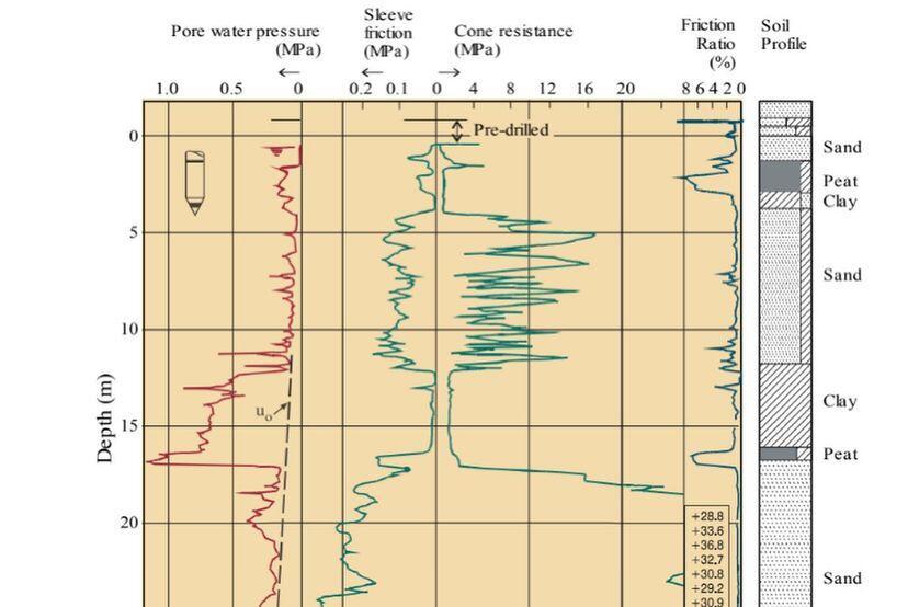
As evidenced by the results of the pile tests, the cone penetrometer estimates for the short-term load capacity can be as low as 20% of the long-term load capacity. One of many equations suggested in the literature can be used to predict the cone sleeve resistance if it is not measured. Some of these are as follows:
For both open-ended and closed-ended driven pipe piles, the skin frictional stress (Lehane et al., 2005) is given as;
fs = CsqcArs × [max(2, h/D)]-0.5 × tan (δcv) ——– (10)
where Cs is a constant (0.03 for compression piles and 0.0225 for tension piles), h is the distance of the pile section under consideration above the pile base, δcv is the soil–pile interface friction angle correlated to the mean particle size (≈23° for D50 = 1 mm, increasing to 28.88 for D50 = 2 mm for sand on steel) and Ars is the effective area ratio of the pile shaft given as;
Closed-ended pipe piles: Ars = 1
Open ended piles: Ars = 1 – min{1, (Di/1.5)0.2} (Di/D)2
Other relationships that have been developed by several other authors are as follows;
Eslami and Fellenius (1997):
fs = Csqcs ——– (11)
where qcs is the cone resistance after adjustments for porewater pressure measured at the cone shoulder, and Cs is a coefficient that depends on soil type, as shown in the Table below;
| Type of soil | Cs |
| Soft, sensitive soils | 0.08 |
| Clay | 0.05 |
| Stiff clay and mixture of clay and silt | 0.025 |
| Mixture of silt and sand | 0.01 |
| Sand | 0.004 |
Vesic (1977) —coarse-grained soils:
fs = 0.11 exp(-3 tan ϕ’cs)qc ——– (12)
Jardine et al. (1998) —coarse-grained soils:
fs = σ’rc tan ϕi ——– (13)
where σ’rc is the radial effective stress on the shaft and is empirically related to the cone resistance.
Tumay and Fakhroo (1984) —stiff clays:
fs = 0.5qc ——– (14)
The ultimate skin friction is;
Qf = fs × perimeter × length
You have to exercise caution in using these empirical equations, as they were derived from pile load tests and cone penetrometer data in particular soil types and locations.
Worked Example: Pile Load Capacity Using SPT Data
A 350 x 350 mm closed-ended square pile is driven into a sand profile to a depth of 10 m. The SPT results are shown in the table below. Estimate the allowable load capacity for a factor of safety of 3.
| Depth (m) | 1 | 3 | 5 | 6 | 8 | 10 | 11 | 13 |
| N60 (blows/300 mm) | 22 | 18 | 25 | 20 | 30 | 36 | 39 | 45 |
Use Meyerhof (1956) equations for displacement piles since the pipe pile is closed-ended.
Solution
Step 1: Determine the skin friction
N60 = average N60 = (22 + 18 + 25 + 20 + 30)/5 = 23
Displacement pile: fs = 1.9N60 = 1.9 × 23 = 44 kPa < 100 kPa; use fs = 44 kPa
qf = fs × perimeter × length = 44 × 4(0.35) × 10 = 616 kN
Step 2: Determine the end bearing and allowable load capacity.
fb = CN60 (kPa);
C = 38(Ls/D) = 38(10/0.35) = 1085 > 380
Use C = 380
N60 = 36 (this is the N value at the base)
Qb = fbAb = 380 × 36 × 0.35 × 0.35 = 1675.8 kN
Qult = Qf + Qb = 616 + 1675.8 = 2291.8 kN
Qa = Qult/FS = 2291.8/3 = 763.93kN




great article. this information will come in handy on our upcoming deep foundation project
That is very great to hear