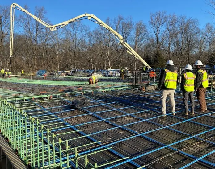
Post-tensioning is a type of prestressing that involves tensioning the tendons after the concrete has hardened, and predominantly transferring the prestressing force to the concrete through the end anchorages. The strength of concrete members is commonly enhanced by post-tensioning, which is a prestressing technique commonly used by engineers.
In post-tensioned concrete, compressive stresses are introduced into the concrete in prestressed members to lower tensile stresses induced by applied loads, such as the member’s own weight (dead load). Compressive stresses are applied to the concrete by means of prestressing steel, such as strands, bars, or wires.
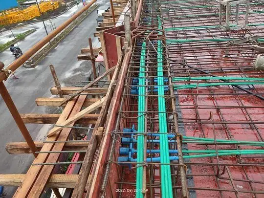
Construction of post-tensioned concrete members
In post-tensioned concrete, the concrete is cast around hollow ducts that are fitted to any desired profile after the formwork is in place. Normally, the steel tendons are in the ducts during the concrete pour, unstressed in them. However, they can also be threaded through the ducts at a later point in time. Tendons are tightened after the concrete reaches the desired strength. Tendons can either be stressed from both ends, or from one end while the other is anchored.
At each stressed end of the concrete element, the tendons are then anchored. After the tendons are anchored, the prestress is maintained by bearing the end anchorage plates onto the concrete, which compresses the concrete during the stressing operation. Every time the cable’s direction changes, the post-tensioned tendons impose a transverse force on the member.

The tendons’ ducts are frequently filled with grout under pressure once they have been anchored and confirmed that no further stressing is needed. In this way, the tendons are bonded to the concrete and are more efficient in controlling cracks and providing ultimate strength. If a tendon is later lost or damaged, bonded tendons are also less prone to corrode or cause safety issues.
However, there are instances where tendons are not grouted for economic reasons and remain permanently unbonded. The tendons are grease-coated and enclosed in a plastic sleeve in this method of construction.
Unbonded post-tensioned slabs are frequently utilized in North America and Europe, despite the fact that they provide only around 75% of the ultimate strength of a beam or slab that is provided by bonded tendons. Post-tensioning is the most common in in-situ prestressed concrete. Relatively light and portable hydraulic jacks make on-site post-tensioning an attractive option.
Applications of post-tensioning
Prestress is typically applied on-site to a variety of structures using post-tensioning of concrete. Members such as slabs and beams are easily post-tensioned on site. Large-span bridge girders are segmentally built using post-tensioning as well.
When a structure is post-tensioned, there is a great deal of flexibility in how the prestress is delivered since the tendon profiles may be easily changed to match the applied loading and the support circumstances. Stage stressing, which involves applying incremental prestress as needed at various building stages as the external stresses progressively rise, is also well suited to post-tensioning.
Components of post-tensioned systems
The components of post-tensioned systems are prestressing strands, anchorages, corrugated galvanized steel or plastic ducts (including grout vents for bonded tendons), and grout. The ducts are fixed to temporary supports (typically attached to the non-prestressed reinforcement of a beam) at strategic intervals throughout the formwork to create the post-tensioned tendon profile.
The strands are typically supported on bar seats for slabs on the ground. As shown in Figure 3, respectively, the ducts that contain the prestressing tendons may be made of plastic ducting or corrugated steel sheathing in more modern innovations.
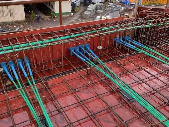
In a typical continuous floor slab, a post-tensioning strand is laid out schematically in Figure 4. A continuous beam would likewise be covered by the details. The design loads, as well as the placement and kind of supports, determine the prestressing tendon’s profile. The concrete is given time to cure after casting until it reaches the necessary transfer strength.

Depending on the system being used or the requirements of the structural design, an initial prestressing force may be applied when the concrete compressive strength reaches about 10 MPa (to facilitate the removal of forms), and the strands will then be re-stressed up to the initial jacking force when the concrete has reached the required strength at transfer.
The grouting of the ducts following the post-tensioning procedure is a common practice in many regions of the world. At one end of the duct, grout is injected into it under pressure. To make sure that the wet grout completely fills the duct during the grouting operation, grout vents are placed at various points along the duct (as illustrated in Figure 4).
The post-tensioned tendon is essentially bound to the surrounding concrete once the grout has dried and set. The grout has various benefits, including enhanced tendon corrosion protection, increased prestressing steel utilization in bending under ultimate limit state conditions, and—most importantly—prevention of tendon failure owing to localized damage at the anchorage or an unintentional strand cutting.
A hydraulic jack working on the concrete at the stressing anchorage at the member’s one end (commonly referred to as the live end) is used to apply the prestress (Figure 5). Figure 5 shows a hydraulic jack stretching the multi-strands in a duct.

An anchor head, accompanying wedges needed to secure the strands, and an anchorage casting or bearing plate make up the live end of a post-tensioning anchorage system (see Figure 2). Although these anchorages exist in a variety of sizes and shapes, their load transmission mechanism generally stays the same. The hydraulic jack pulls the strands sticking out behind the anchorage during the stressing process until the necessary jacking force is attained. Figures 3.6d and e depict typical live-end anchorages for a flat ducted tendon.
Figures 5 and 36 depict the wedges used to clamp the prestressed strands at the live end of a slab tendon prior to post-tensioning. The strands are typically painted prior to post-tensioning to make it easier to evaluate each strand’s elongation following the stressing procedure. The wedges in the anchor head secure the post-tensioned strands after jacking, and the anchor casting or bearing plate transfers the load from the jack to the structure.

When just one end of the member needs to be stressed, the non-stressing end is frequently in the form of an internal dead-end anchoring, where the ends of the strands are cast in the concrete (see Figure 7). This is true even if the live anchorage can also be utilized at an exterior non-stressing end.
Despite the fact that there are numerous variations on this anchorage, the basic idea is to use either swaged barrels bearing on a steel plate or extending out the exposed strand bundle to generate local anchor nodules or bulbs at the extremities beyond the duct.

To stop concrete from entering the duct during construction, it is sealed. Only after the surrounding concrete has acquired the necessary transfer strength is the tendon stressed. Figure 5 illustrates common anchorage systems for use with multi-strand setups. Following the completion of the stressing, the strands are cut off. Tendons within a member can be connected using tendon couplers and intermediate anchorages.
Grouting of the tendons
The durability of the structure depends on a well-designed grout mix and well-grouted tendons. The positioning of the grout vents, which are used to inject grout and release air from the duct at grout outlets, is one of many elements that determine whether a grouting operation is successful.
As the grout is injected into the duct at the tendon end or anchorage point, vents are needed at the high points of the tendon profile to release the air. Air and water can be evacuated from the crest of the duct profile using vents at or close to the high points. The vent at the far end of the duct emits grout, indicating that the duct is entirely filled with grout.

The installation of either temporary or permanent grout caps guarantees that the anchorages are completely filled and enable later grouting verification. Grout vents are frequently seen at the duct’s high points over the internal supports and at the end anchorages (as illustrated in Figure 4). The ducts into which the grout is injected must be big enough to allow for simple strand installation and unhindered grout flow during the grouting process.
Before grouting the duct, an air pressure test is typically conducted to ensure that the risk of grout leaking is reduced. Grouting has a set process and requires skilled labourers to be effective. The grout is continuously and continuously injected into the duct intake.
The vent is not shut off when the grout emerges from it until the emerging grout has the same viscosity and consistency as the grout being pumped into the intake. After confirming that the grout has the necessary consistency and viscosity, intermediate vents along the tendon are closed sequentially.

