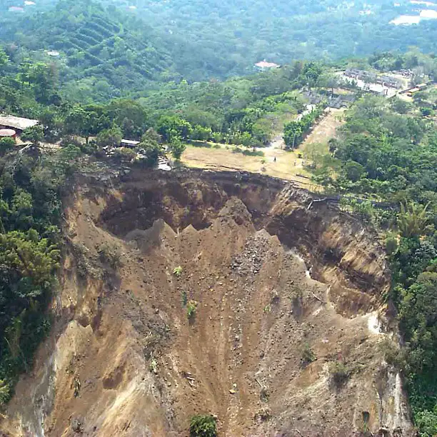
An earth slope can be either a naturally occurring incline or one that is artificially constructed through excavation or engineered fill to produce an embankment. A slope failure refers to the downward displacement of a section of the slope mass in relation to the mass below the sliding surface. Therefore, slope stability assessment is an important aspect of earthworks and geotechnical designs in civil engineering works.
The magnitude of a slope failure ranges from a few meters in height to the displacement of a substantial portion of a high land or mountain. An instance of this is the 1974 Rio Mantaro landslide in Peru, which consisted of a sliding mass of 6 kilometres in length, 2 kilometres in height, and a volume of 1.5 billion cubic meters.
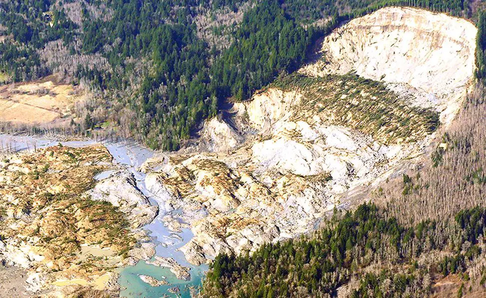
Figure 1 shows a significant slope failure that took place in Oso, Washington, USA, on March 22, 2014. The failure surface displays a rotational sliding surface.
This article focuses on the stability analyses of unreinforced soil slopes under static loading.
Causes of Slope Failure
A slope failure occurs when the external shear stress (or sliding moment) exceeds the internal shear strength (or resisting moment) of the slope.
Shear stress > Shear strength or:
Rotational moment > Resisting moment
The following factors may increase the shear stress or sliding moment:
- Additional surcharge at the top of a slope.
- Application of lateral force that may be caused by seepage, earthquake, or pile driving.
The following factors may decrease the shear strength or resisting moment of a slope:
- Weathering of a rock slope.
- Discontinuities such as weak seams and faults that are developed in the slope.
- Saturation of the slope.
- Removal of lateral support of the slope, for example, the cut toe of a slope.
Types of Slope Failure
Slope failures can be classified into different types based on the shape of the failure surface and the nature of the slope movement.
- Surficial (or translational) slope failure: The sliding surface is parallel to the slope surface. This type of failure can occur when there is a weak layer of soil or rock beneath the surface, or when a loose topsoil layer rests on a hard subsoil layer.
- Rotational slope failure: A large mass of the slope rotates along a curved failure surface. This type of failure is often caused by heavy rainfall or by excavation at the toe of the slope.
- Landslide: A landslide is a large-scale slope failure that can involve multiple types of slope movements. Landslides can be caused by a variety of factors, including heavy rainfall, earthquakes, and volcanic eruptions.
- Lateral spread: Lateral spread is the lateral movement of a fractured soil mass. It is typically caused by earthquakes.
- Debris flow: A debris flow, or mudslide, is a rapid movement of soil that is entrained by flowing water or wind. Debris flows are often triggered by heavy rainfall.
- Creep: Creep is a slow and almost imperceptible movement of the failure portion of a slope. It can be caused by a variety of factors, including gravity, groundwater flow, and frost heave.
- Rock falls: Rock falls occur when rocks on a slope are mobilized by wind, runoff, or gravity. Rock falls can be very dangerous, as they can travel at high speeds and cover long distances.

Slope Stability Analysis
Slope stability analysis methods typically use the limit equilibrium approach, which means that the forces or moments that cause a slope to fail (slide) are balanced by the forces or moments that resist the slope from sliding. This is known as the critical condition. A factor of safety (FS) is used to measure slope stability and is based on the force or moment equilibrium.
FS = 𝜏f/𝜏
or:
FS = Mresist/Mslide
where;
𝜏f = the maximum shear stress at failure, which is equal to the shear strength,
𝜏 = shear stress that causes the sliding of a failure portion, which is caused by external loads such as gravity, foundation loading, seismic force, etc.,
Mresist = total resisting moments that resist a rotational sliding,
Mslide = total sliding moments that cause a rotational sliding.
In general, a value of 1.25–1.5 is used as an acceptable factor of safety. Alternatively, within the context of limit state design, it should be mentioned that:
Ed ≤ Rd
where;
Ed = design effect of the actions (e.g., sliding forces)
Rd = design resistance (dependent on soil strength)
The shear strength is expressed by the Mohr–Coulomb failure criterion:
𝜏f = c + 𝜎 tan 𝜙
where;
𝜎 = total normal stress,
c = soil’s cohesion based on the total stress,
𝜙 = soil’s internal friction angle based on the total stress.
The Mohr–Coulomb failure criterion can also be expressed using the effective stress:
𝜏f = c′ + 𝜎′ tan 𝜙′
There are two main approaches for analyzing slope stability: the total stress method and the effective stress method. The total stress method uses undrained shear strength parameters (c and ϕ), while the effective stress method uses drained shear strength parameters (c′ and ϕ′)
In slope stability analyses, two “artificial” factors of safety are defined on the basis of c and 𝜙, respectively:
FSc = c/cm
FS𝜙 = tan 𝜙/tan 𝜙m
where;
FSc = factor of safety on the basis of c,
FS𝜙 = factor of safety on the basis of 𝜙,
cm = mobilized cohesion that is actually developed along a slip surface, also denoted as cd,
𝜙m = mobilized internal friction angle that is actually developed along a slip surface, also denoted as 𝜙d.
In slope stability analysis, partial factors of safety can be used to account for uncertainties in the soil properties and the loading conditions. These factors are similar to those used in other engineering design codes. In a stable slope, not all of the soil’s strength is needed to resist the forces that cause it to slide.
The mobilized shear strength, which is the amount of shear strength that is actually used to resist sliding, is always less than or equal to the peak shear strength. This means that there is always a factor of safety built into the design of a stable slope. The developed or mobilized shear strength that is needed for slope stability is represented by cm and 𝜙m. Therefore, cm ≤ c and 𝜙m ≤ 𝜙.
At equilibrium, the developed or mobilized shear stress can be expressed as:
𝜏m = cm + 𝜎 tan 𝜙m
At the critical condition, the entire shear strength is needed for equilibrium. So, cm = c, and 𝜙m = 𝜙. Therefore, the minimum value for both FSc and FS𝜙 is 1.0.
If: FSc = FS𝜙 = a (constant)
Then: c = a⋅cm, and tan 𝜙 = a⋅tan𝜙m
FS =𝜏f/𝜏m = (c + 𝜎 tan 𝜙)/(cm + 𝜎 tan 𝜙m) = a
So ∶ FS = FSc = FS𝜙
Methods of Analysis of Slope Stability
Different methods can be used in the analysis of stability of slopes. The methods can be generalised as;
- Mass methods
- Methods of slices
- Finite element methods
In the mass methods, the sliding soil mass is analyzed as one entity. The mass methods are applicable only to homogeneous slopes and can be employed in the analysis of finite and infinite slopes. In the analysis of finite slope, Culmann’s method is normally used for planar failure surfaces, while Taylor’s chart and Michalowski’s chart are used for curved failure surfaces.
In the methods of slices, the sliding soil mass is divided into numerous slices and the stability of each slice is analyzed. Then all the slices are combined to derive the factor of safety of the slope for the assumed failure surface. To obtain the true factor of safety of the slope, numerous trial surfaces are analyzed that provide the minimum factor of safety. The methods are applicable to homogeneous or heterogeneous slopes.
The popular methods in this category are the ordinary method of slices (Fellenius method of slices), Bishop-simplified method of slices, Bishop and Morgensten method, Spencer method with consideration of pore water pressure, Morgenstern charts for rapid drawdown, etc.
The finite element method involves modelling the soil using finite elements and simulating the failure of the slope. Computer packages such as Plaxis are capable of such models.
Method of Slices
The method of slices is a numerical procedure that has been developed to handle stability analysis of slopes where conditions are nonhomogeneous within the soil mass making it impossible to deduce closed-form solutions. Some of the non-homogeneous conditions commonly encountered are irregularity of failure planes, variable soil properties, significant variation in the distribution of pore pressure along the failure plane, irregular slope geometry, etc.
The analysis requires the selection of a trial failure plane and discretization of the resulting failure wedge into a convenient number of slices as shown in Figure 3.

The analyst is required to devise the slicing in a manner that can incorporate any nonhomogeneity within the slope so that each resulting slice would be a homogeneous entity. Then, the stability of each slice can be analyzed separately using the limit equilibrium method and principles of statics. The static analysis of the slices can be obtained in most geotechnical engineering textbooks.
Assumptions of the Method of Slices
The method of slices makes several simplifying assumptions to facilitate analysis:
- The slope is divided into vertical slices of uniform or variable thickness.
- The failure surface is assumed to be planar or circular for simplicity.
- The soil within each slice is assumed to be homogeneous and isotropic.
- The normal and shear stresses at the base of each slice are assumed to be uniformly distributed.
- Interslice normal and shear forces are neglected or assumed to be constant.
The factor of safety of the slope on any assumed circular slip surface using the method of slices is:

The ordinary method of slices assumes that the interslice forces on both sides of each slice cancel one another. Therefore, the factor of safety derived from this method is overconservative and is lower than other methods of slices.
Worked Example
Calculated the factor of safety of the earth slope shown in Figure 4 using the ordinary method of slices. Assume the failure circle shown in Figure 5.
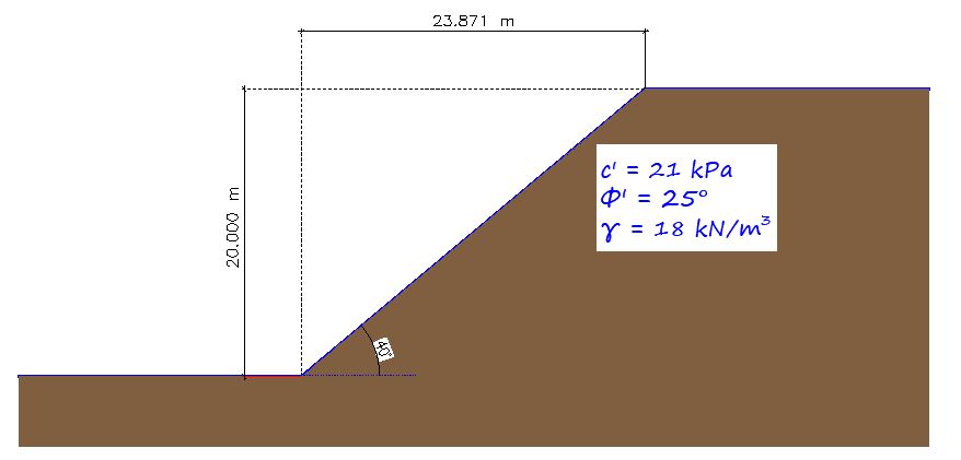
The selected failure surface and the number of slices are shown in Figure 5.

The solution can be presented in the tabular form shown below;
| Slice No [1] | Area (m2) [2] | Slice Weight (kN/m) [3] | α (degrees) [4] | b (m) [5] | cos α [6] | sin α [7] | b/cos α (m) [8] | Wsin α (kN/m) [9] | Wcos α (kN/m) [10] |
| 1 | 13.121 | 236.178 | 61 | 3.645 | 0.485 | 0.874 | 7.515464 | 206.4196 | 114.5463 |
| 2 | 29.829 | 536.922 | 49 | 4 | 0.656 | 0.754 | 6.097561 | 404.8392 | 352.2208 |
| 3 | 32.108 | 577.944 | 39 | 4 | 0.777 | 0.629 | 5.148005 | 363.5268 | 449.0625 |
| 4 | 30.006 | 540.108 | 30 | 4 | 0.866 | 0.5 | 4.618938 | 270.054 | 467.7335 |
| 5 | 23.794 | 428.292 | 22 | 4 | 0.9271 | 0.375 | 4.314529 | 160.6095 | 397.0695 |
| 6 | 16.095 | 289.71 | 14 | 4 | 0.97 | 0.242 | 4.123711 | 70.10982 | 281.0187 |
| 7 | 5.717 | 102.906 | 7 | 4 | 0.9925 | 0.121 | 4.030227 | 12.45163 | 102.1342 |
| Total | 35.84843 | 1488.01 | 2163.786 |
The factor of safety can then be calculated thus;
FS = (c∑col[8] + ∑col[10]tan𝜙)/∑col[9]
FS = (21 × 35.848 + 2163.786 tan 25)/1488.01 = 1761.794/1488.01 = 1.18
Conclusion
Slope stability analysis is a crucial aspect of geotechnical engineering, ensuring the stability of natural slopes, embankments, and excavations. It evaluates the likelihood of a slope failure, which can have catastrophic consequences for infrastructure, property, and human safety.
The most common approach to slope stability analysis is the limit equilibrium method, which assumes that the slope is either in a state of equilibrium or on the verge of failure. It involves calculating the driving forces that cause the slope to slide (e.g., gravitational forces) and the resisting forces that prevent sliding (e.g., shear strength of the soil).
The method of slices is a widely used limit equilibrium technique for analyzing slope stability. It involves dividing the slope mass into a series of vertical slices and analyzing the forces acting on each slice. The forces acting on each slice include its weight, the normal and shear forces at its base and sides, and any external forces such as water pressure.

