Typical structures are rarely supported only on a single pile. Therefore, the number and spacing of piles required to support a given structure is an important aspect of the design. The number of piles required to support a given load is dependent on the magnitude of the load and the load-carrying capacity of the piles, while the spacing of piles in a group is dependent on the type of pile, soil properties, method of installation, and the size of the pile.
However, in some cases, lightly loaded columns in a building or other structures can be supported on a single pile, provided the piles and pile caps are eventually chained together with continuous ground/plinth beams. In such cases, the load-carrying capacity analysis of the pile can be based on the case of a single pile.
In other cases, the group of piles are typically positioned in close spacing beneath the structures they support, thereby necessitating the consideration of the collective behaviour of the entire group of piles. This is especially important when friction piles are used. The bearing capacity of a pile group does not solely depend on the capacity of each individual pile multiplied by the number of piles in the group. This difference in capacity is attributed to the phenomena known as ‘Group action of piles’.
Grouping of Piles
It is typical to avoid the exclusive usage of driven piles beneath a column or wall due to the tendency of the pile to deviate horizontally during installation, leading to uncertainty in aligning the pile accurately beneath the foundation. Failure can occur either at the interface between the pile and column or within the pile itself, when unexpected eccentricities arise.
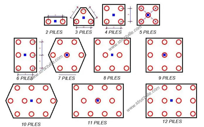
Therefore, it is usual practice to construct piles for walls in a staggered configuration on both sides of the wall’s centre line. When a single pile configuration is not feasible, a higher number of piles are utilized in a specific configuration for supporting a column. If the needed capacity exceeds three piles, the piles will be arranged symmetrically around the point or area where the load is applied. Figure 1 illustrates the representative configurations of pile groups for column loads.
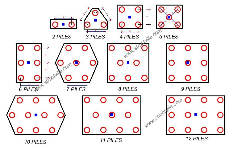
Typically, column and wall loads are transmitted to the pile group by means of a pile cap. This pile cap is a thick reinforced concrete slab that is connected to the pile heads, facilitating the collective behaviour of the group (see Figure 2).
The requirement for the collective arrangement of driven piles does not extend to bored piles. Drilled shafts can be placed with a high degree of precision. Residential buildings can utilize a single, large-diameter drilled shaft pile to provide support for its columns. This can be utilized when the arrangement of three piles results in an excessive amount of additional load capacity, particularly in the scenario of driven piles.
In a typical scenario, the number of piles required to support any load is calculated using the serviceability limit state loads. This is then compared with the stated safe load-carrying capacity of a given pile with known diameter and embedment depth. For instance, if the calculated service axial load is 2450 kN, and the load carrying capacity of a 600 mm diameter pile at an embedment depth of 15 m is 724 kN, the number of piles required is given by;
Number of piles = Service Axial Load/Allowable pile load capacity = 2450/724 = 3.38 (Adopt 4 piles)
Spacing of Piles
The spacing of piles in a group is determined by several criteria, including the overlapping of stresses between adjacent piles, the cost of the foundation, and the intended efficiency of the pile group. The stress isobars of a single pile supporting a focused load will resemble the illustration in Figure 2(a).
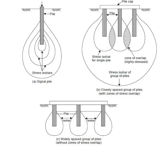
When piles are driven in close proximity, there is a potential for the stress isobars of neighbouring piles to overlap, as illustrated in Figure 2(b). To prevent potential failure due to either shear or excessive settlement, it is advisable to increase the space between the overlapping elements, as seen in Figure 2(c). Wide spacing is disadvantageous as it necessitates a larger pile cap, hence increasing the overall cost of the foundation.
Driven piles result in increased stress overlap owing to soil displacement. When piles are driven into loose sands, compaction occurs, resulting in smaller spacing. However, in the case of piles being driven into saturated silt or clay, compaction does not occur, but the piles may undergo uplift. To mitigate this issue, one can increase the pile spacing.
Reduced spacings can be employed for cast-in-situ piles due to a decreased tendency for disturbance. End-bearing piles can be positioned at a closer spacing compared to friction piles. Different building codes typically stipulate the minimum spacing between piles. The spacing of straight uniform cylindrical piles may range from 2 times the diameter (2d) to 6 times the diameter (6d). The required minimum distance for friction piles is three times the diameter of the pile (3d).
When point-bearing piles pass through a compressible stratum, the minimum spacing required is 2.5 times the diameter of the piles if they are resting on compact sand or gravel. However, if the piles are resting on stiff clay, the minimum spacing should be 3.5 times the diameter of the piles. The minimum distance required for compaction piles may be 2 times the diameter (2d).
In general, piles should be driven starting from the centre and moving outward, unless the soil is soft clay or very soft. In such cases, the pile driving should start from the edges of the foundation and go towards the centre to prevent the sideways movement of dirt during the driving process.
Take Away
The primary considerations for determining the number of piles include the load-bearing capacity of the soil, the expected loads on the structure, and the desired safety factors. Pile capacity can be estimated through various methods such as static load tests, dynamic load tests, or geotechnical analysis.
Engineers must also consider the distribution of loads across the piles and assess how they interact to distribute the structural loads effectively. Additionally, the structural design of the piles themselves, including their type (e.g., driven piles, drilled shafts, or micropiles), size, and material, may also affect the number of piles needed.
The spacing of piles is equally important. It influences the overall performance of the foundation system, affecting factors like settlement, cost, and load-carrying capacity. When piles are spaced so closely such that the stress isobars overlap, the pile group will undergo higher settlement than previously envisaged. From experience, you rarely go wrong by placing your spacing between 2.5d to 3d. Proper spacing design involves a balance between load distribution and economic considerations.
In conclusion, determining the number and spacing of piles for a foundation system demands careful engineering consideration of soil characteristics, structural loads, safety margins, and economic implications. The chosen arrangement must guarantee the structure’s stability and performance while keeping construction expenses within budget. Selecting the right number and spacing of piles is an important aspect of deep foundation design and has a substantial impact on the overall success of a construction project.





The article is well detailed. We need more drawing details because of young Engineers that needs to see what the article is trying to present because they don’t have enough experience of site works and how it looks like.