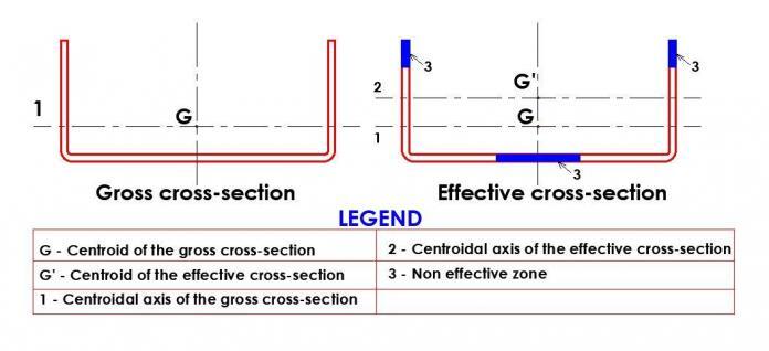
In the design of steel structures, it is necessary to determine the section’s dimensional properties under consideration before a member’s resistance to bending, compression or other types of loading can be calculated. According to Eurocode 3, the section properties usually considered are the effective and gross section properties.
According to clause 6.2.2.1 of EN 1993-1-1, the properties of the gross cross-section should be determined using the nominal dimensions. Holes for fasteners need not be deducted, but allowance should be made for larger openings. Splice materials should not be included. When the effects of holes and openings are considered in the analysis, it is referred to as net section properties.
Effective section properties are the characteristics of a fictitious cross-section whose area has been reduced to account for the effects of local buckling. It can also be essential to make additional reductions to account for distortional buckling. The effective properties of the section are always used to compute the bending and compression resistances of light steel members (cold-formed steel sections such as that found in roof purlins).

Effective Section Properties
According to clause 6.2.2.4 of EN 1993-1-1, when the cross-sections with a class 3 web and class 1 or 2 flanges are classified as effective Class 2 cross-sections, see clause 5.5.2(1) of EN 1993-1-1, the proportion of the web in compression should be replaced by a part of 20εtw adjacent to the compression flange, with another part of 20εtw adjacent to the plastic neutral axis of the effective cross-section in accordance with Figure 6.3 of EN 1993-1-1 (shown below).
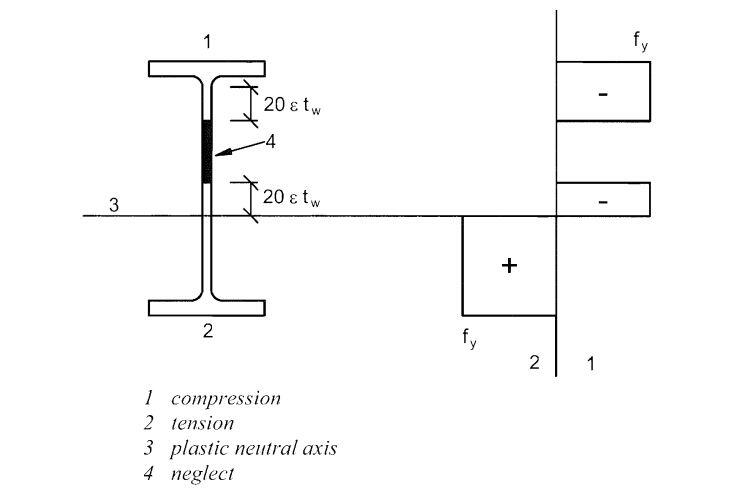
However, the effective cross-section properties of Class 4 cross-sections should be based on the effective widths of the compression parts. For cold-formed sections, it should be based on the requirements of EN 1993-1-3.
For light gauge steel sections, there is an implied presumption that the cross-section belongs to class 4 rather than classifying it (although this term is not used in BS EN 1993-1-3). Using the same methods as for class 4 sections to BS EN 1993-1-1, the design process concentrates on calculating the effective section properties after making this assumption. Effective section characteristics are used to reduce the amount of calculation necessary without too conserving on cross-section resistance by simplifying the intricate stress distributions related to local buckling.
The effective width approach substitutes simplified equivalent stresses acting over two equal widths of beff/2 for the actual stress distribution acting across element width b. It is assumed that there is no stress in the centre of the plate, which is the area most susceptible to local buckling, and it is completely disregarded. The end result is a straightforward model where uniform stress assumed to act over a narrower plate is equal to the steel’s yield strength.
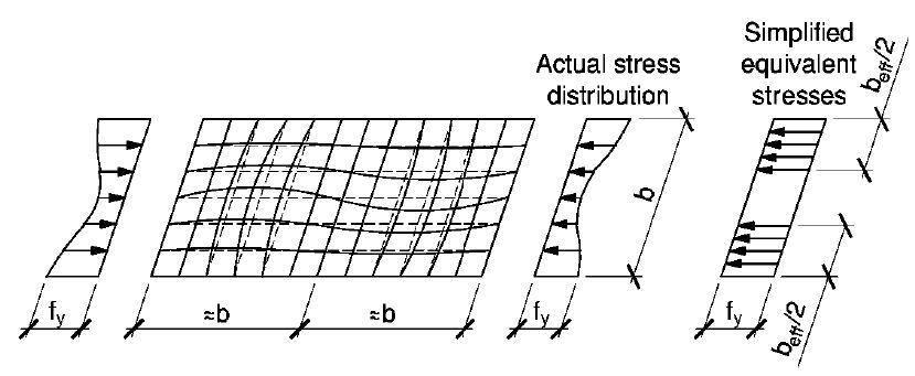
The approach used by BS EN 1993-1-3 applies the above-illustrated effective width idea to the cross-section of a light gauge steel element. Each of the features of the cross-section—flanges, webs, lips, etc.—is treated as the flat plate in the Figure above. Each element that is under compressive stress has its effective width beff determined (either due to applied axial compression or bending).
The effective area of the element Aeff is then obtained by multiplying beff by the section thickness t. Elements not subjected to compressive stress are not susceptible to local buckling, so the full element width b may be used in the calculation of the effective section properties.
Gross Section Properties
The term gross section properties, as the name implies, refers to the entire cross-section without any reduction for local buckling. For the majority of common section shapes, calculating the gross section properties only requires adding up the elemental areas and first and second moments of area (for flanges, web, stiffeners, etc.), determining the major and minor centroidal axes’ locations, and deriving the second moment of area for the entire section from these values. If necessary, a similar procedure can be repeated for additional properties.

