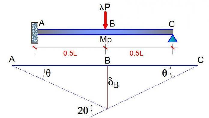
We all know that for a propped cantilever beam, there are two possible locations of plastic hinges – which are at the span (point of maximum moment) and at the fixed support. For the propped cantilever loaded as shown above, the degree is static indeterminacy is 1.
Since the number of possible location of plastic hinges is 2, therefore the number of independent mechanisms is;
P = 2 – 1 = 1 (which is a beam mechanism)
As a result, we are going to carry out our elastic analysis in two stages, so as to determine the load factor at which the beam will form a mechanism and completely collapse. We will start by assuming a value of unity for our load factor (i.e. λ =1.0)
STAGE 1
It is very easy to verify that for the beam loaded as shown above, the fixed end moment at support A = 3PL/16 = (3 × 267 × 8) / 16 = 400.5 KNm
It is also easy to verify that the vertical support reaction at support C (RC) = 5P/16 = (5 × 267)/16 = 83.4375 KNm
Therefore, the maximum span moment at point B (MB) = 83.4375 × 4 = 333.75 KNm
The bending moment is as given below.
We can also obtain the vertical deflection at point B by quickly placing a unit load at point B on a basic system of the structure (could be a cantilever or a simply supported beam). Then by combining the shapes from the two states of loading using Vereschagin’s rule, we can obtain the deflection at point B. This is given below.
EIδB = 1/6 × 4 [2(400.5) – 333.75] × 4 = 1246
δB = (1246/EI) metres
Therefore, for support A to become plastic, the load factor λA1= MP/ME = 500.625/400.5 = 1.25
Also for section B to become plastic, the load factor λB1 = MP/ME = 500.625/333.75 = 1.5
It is therefore obvious that the first plastic hinge will develop at support A.
Therefore the load at failure of support A = 1.25 × 267 = 333.75 KN
λA1MA = 1.25 × 400.5 = 500.625 KN.m
λA1MB = 1.25 × 333.75 = 417.1875 KN.m
Deflection of beam at failure of support A = δB= (1.25 × 1246)/EI= (1557.5/EI metres)
STAGE 2
Now, support A is assumed to have failed (formed a plastic hinge). We now model it as a real hinge and carry out another elastic analysis.
From statics, the maximum moment of the structure is given by;
PL/4 = ( 267 × 8)/4 = 534 KNm
For section B to become plastic and form a hinge;
λB2 = (MP – λA1MB)/ME = (500.625 – 417.1875) / 534 = 0.15625
Therefore, the total load factor at collapse (λ) = λA1 + λB2 = 1.25 + 0.15625 = 1.40625
Also, the load at complete collapse of the beam = 1.40625 × 267 = 375.468 KN
The deflection at collapse = δB= (1.40625 × 1246) / EI= (1752.1875/EI) metres
Verification using the static method
From geometrical relations, you can observe that δB = 4θ
Internal work done due to rotations of the structure at full plastic moment = MPθ + MP(2θ) = 3MPθ (the rotation at section C will not count because it is a natural hinge).
External work done by the collapse load = 375.468 × 4θ = 1501.871θ
But External work done = Internal work done;
Therefore, 3MP θ = 1501.871θ
Therefore, MP = 1501.871/3 = 500.624 KNm
This shows that the load factor we obtained from our analysis is correct.
For more interesting articles and complete follow up, like our Facebook page;


Great Job and information.
Thank you and keep visiting… God bless
Thumbs up… Keep your great work going.
Thank you so much, continue visiting and remember to always share with your colleagues
Nice. Keep it up.
Thank you
I have been following you helpful posts. It will be tremendously of big help if you could do push-over analysis of a one-storey 2D portal frame. I have seen lots of books but they seem to hide the real steps of doing such analysis.
• Hey very cool web site!! Man.. Beautiful.. Wonderful.. I will bookmark your website and take the feeds additionally? I am happy to find a lot of helpful information here within the put up, we need work out extra techniques on this regard, thanks for sharing. .
BIM Project Management in USA
BIM Implementation in USA
BIM Solutions in USA
BIM Consulting in USA
BIM documentation in USA
BIM Implementation in USA
Good brief resolution!