Doubly reinforced beams are reinforced concrete beams that incorporate both compression steel (in the compression zone) and tension steel (in the tension zone). This design is typically employed when the required moment capacity of a beam exceeds that which can be provided by singly reinforced beams (those with only tension steel).
In singly reinforced concrete beams without moment redistribution, k = MEd/fckbd2 is limited to k’ = 0.167. Therefore, once the value of k > k’, the beam must be designed as a doubly reinforced beam. In doubly reinforced beams, compression steel reinforcements are required because the concrete section (in compression) by itself cannot develop the required moment of resistance.
However, when there is a moment redistribution in the section, k > k’ where k’ is dependent on the moment redistribution ratio (δ) and is given by:
k’ = 0.6δ – 0.18δ2 – 0.21 where δ ≤ 1.0
In all cases, it is recommended that k’ be limited to 0.167 to ensure ductile failure. It is important to understand that the redistribution of moments derived from elastic analysis of a reinforced concrete structure accounts for the plastic behaviour of the material as it approaches its ultimate limit state.
To facilitate this plastic response, concrete sections must be designed to permit the formation of plastic hinges upon the yielding of tensile reinforcement. This approach ensures a ductile structure characterized by a gradual failure at the ultimate limit state, rather than a sudden, catastrophic collapse due to compressive failure of the concrete.
To guarantee the formation of plastic hinges and the necessary section rotation for ductile behaviour, Eurocode 2 imposes limitations on the maximum neutral axis depth, xbal. These restrictions ensure that the tensile steel experiences high strains and this promotes the desired plastic response.
The permissible value of xbal is determined based on the desired degree of moment redistribution. According to Eurocode 2, the limit is xbal ≤ 0.8(δ – 0.44)d for fck ≤ C50. However, this limit was modified to xbal as xbal ≤ (δ – 0.4)d in the UK Annex to the EC2.
Design of Doubly Reinforced Beam
To ensure a ductile response and prevent sudden compressive failure of the concrete, it is required that the neutral axis depth should not exceed 0.45 times the effective depth (0.45d). This guideline is typically adopted in the design of sections incorporating compression reinforcement (doubly reinforced beam sections).

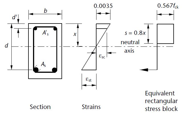
In the design of reinforced concrete beams, if the design ultimate moment is greater than the ultimate moment of resistance i.e. MEd > Mlim, then compression reinforcement is required. Provided that d2/x ≤ 0.38 (i.e. compression steel has yielded) where d2 is the depth of the compression steel from the compression face and x = (d − z)/0.4
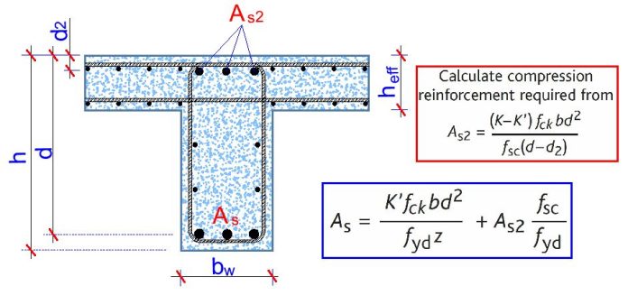
The area of steel in compression, As2, is given by:
As1 = (MEd – Mlim) / (fsc(d – d2)) —- (1)
fsc = Esεsc ≤ 0.87fyk
εsc = steel compressive strain = 0.0035(x – d’)/x
Es = Modulus of elasticity of steel = 200000 N/mm2
Area of tension reinforcement:
As1 = Mlim / (0.87fykz) + As2 (fsc/0.87fyk) —- (2)
Where:
MEd = Design bending moment of the section
Mlim = 0.167fckbd2
z = d[0.5+ √(0.25 – 0.882k’)]
where
k’ = 0.167
Design Example of a Doubly Reinforced Beam
To show how this is done, let us consider the flexural design of support A of the beam loaded as shown below. The depth of the beam is 600 mm, and the width is 400 mm.
fck = 35 N/mm2 ; fyk = 500 N/mm2; concrete cover = 40mm
Top reinforcement (Hogging moment)
Support A (No moment redistribution)
Effective depth (d) = 600 – 40 – 16 – 10 = 534 mm
d2 = 40 + 8 + 10 = 58 mm
MEd = 761.24 kNm
But since the flange is in tension, we use the beam width to calculate the value of k (this applies to all support hogging moments)
k = MEd / (fckbwd2) = (761.24 × 10⁶) / (35 × 400 × 5342) = 0.1906
z = d[0.5+ √((0.25 – 0.882(0.167))] = 0.82d = 0.82 × 534 = 437.88 mm
x = (d − z)/0.4 = (534 − 437.88)/0.4 = 240.3 mm
d2/x = 58/240.3 = 0.241 < 0.38 (therefore reinforcement bar has yielded and fsc = 0.87fyk)
Since k < 0.167, compression is required
Area of compression reinforcement AS2 = (MEd – Mlim) / (0.87fyk (d – d2))
Mlim = 0.167fckbd2 = (0.167 × 35 × 400 × 5342) × 10-6 = 666.69 kNm
AS2 = ((761.24 – 666.69) × 106) / (0.87 × 500 × (534 – 58)) = 457 mm2
Provide 3H16 Bottom (Asprov = 603 mm2)
Area of tension reinforcement As1 = MRd / (0.87fyk z) + AS2
Where z = d[0.5+ √(0.25 – 0.882K’)]
K’ = 0.167
z = d[0.5+ √((0.25 – 0.882(0.167))] = 0.82d
As1 = MRd / (0.87fyk z) + AS2 = ( 666.69 × 10⁶) / (0.87 × 500 × 0.82 × 534) + 457 mm2 = 3957 mm2
Provide 3H32mm + 4H25 mm Top (ASprov = 4376 mm2)


• I have read a few good stuff here. Definitely value bookmarking for revisiting. I wonder how a lot effort you put to make this type of fantastic informative website.
bim services
bim servicesin USA
bim servicesin Uk