The predominant cause of deformation in beams subjected to externally applied load is bending, and that is one of the most popular analytical methods for beams with small deflection. However, additional deformation is induced in beams due to shear forces in the form of mutual sliding of adjacent sections across each other. As a result of the non-uniform distribution of shear stresses, the sections previously plane now become curved due to shearing alone.
Beams that are analysed by considering elastic deformation due to bending are known as Euler-Bernoulli beams, while beams that are analysed considering bending and shear deformations are known as Timoshenko beams. Timoshenko beam theory is useful in the analysis of thick beams.
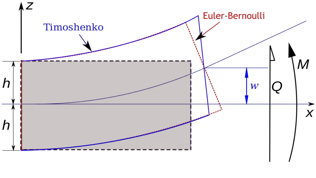
In this article, we are going to present some solved examples on the shear deformation of one-span beams due to externally applied load. Using the simple virtual work method and employing Verecshagin’s combination rule, we are going to calculate the deflection at the critical points of some beams due to bending and due to shear forces. You will discover why shear deflection is neglected in some cases, but in sections that are significantly deeper, shear forces can be quite influential.
The displacement equation due to shear forces is given below;
Where;
k = factor that accounts for non-uniform distribution of shearing stresses. For rectangular sections, k = 3/2, and for circular sections, k = 3/4
G = Shear modulus of the section
A = Area of the cross-section
Q = Shear force due to externally applied load
Q ̅ = Shear force due to a unit virtual load at the point where the deflection is sought
Similarly, the displacement equation due to bending moment is given below;
Where;
E = Elastic modulus of the section
I = Moment of inertia of the cross-section
M = Bending moment due to externally applied load
M ̅ = Bending moment due to a unit virtual load at the point where the deflection is sought
Solved Examples
For all examples shown below, the section shown below will be used for all calculations.
Geometrical Properties
Area (A) = bh = 0.2m × 0.4m = 0.08 m2
Moment of inertia (I) = bh3/12 = (0.2 × 0.43)/12 = 0.0010667 m4
E = 21.7 KN/mm2 = 21.7 × 10⁶ KN/m2
G = E / 2(1 + ν) = (21.7 × 10⁶)/2(1 + 0.2) = 9.0416 × 10⁶
Flexural rigidity EI = (21.7 × 106) × 0.0010667 = 23147.39 KN.m2
Shear stiffness GA = (9.0416 × 106) × 0.08 = 723333.333 KN
Example 1: Shear deflection of a simply supported beam carrying a uniformly distributed load
The internal forces diagram due to externally applied load is shown below;
Removing the external load and placing a unit load at the mid-span, we can plot the internal stresses diagram as shown below;
We can now obtain the deflection at the mid-span by diagram combination;
(a) Deflection due to bending;
EIδb1 = 2 [5/12 × 62.5 × 1.25 × 2.5] = 162.760
δb1 = 162.760/23147.39 = 0.0070314 m = 7.0314mm
(b) Deflection due to shear;
GAδs1 = 2 [3/2 × 1/2 × 50 × 0.5 × 2.5] = 93.75
δs1 = 93.75/723333.333 = 0.0001296 m = 0.1296 mm
Example 2: Shear deformation of a simply supported beam carrying a concentrated load at the mid-span.
The internal forces diagram due to externally applied load is shown below;
Placing a unit load at the mid-span and plotting the internal stresses diagram;
We can now obtain the deflection at the mid-span by diagram combination;
(a) Deflection due to bending;
EIδb2 = 2 [1/3 × 125 × 1.25 × 2.5] = 260.417
δb2 = 260.417/23147.39 = 0.01125 m = 11.25 mm
(b) Deflection due to shear;
GAδs2 = 2 [3/2 × 50 × 0.5 × 2.5] = 187.5
δs2 = 187.5/723333.333 = 0.0002592 m = 0.2592 mm
Example 3: Shear deformation of Cantilever beam carrying a uniformly distributed load
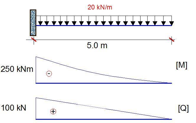
Placing a unit load at the free end and plotting the internal stresses diagram;
We can now obtain the deflection at the mid-span by diagram combination;
(a) Deflection due to bending;
EIδb3 = [1/4 × 250 × 5 × 5] = 1562.5
δb3 = 1562.5/23147.39 = 0.0675 m = 67.502 mm
(b) Deflection due to shear;

GAδs3 = [3/2 × 1/2 × 100 × 5 × 1.0] = 375
δs3 = 375/723333.333 = 0.00051843 m = 0.5184 mm
As you can see in all the examples we considered, there was no case where the additional deflection due to shear was up to 1 mm, and for practical purposes, they are very negligible for normal one span beams. Watch out for future posts where we will present cases where shear deflection becomes significant.
Thank you for visiting www.structville.com. We hope you visit us again, and share this post with your friends.

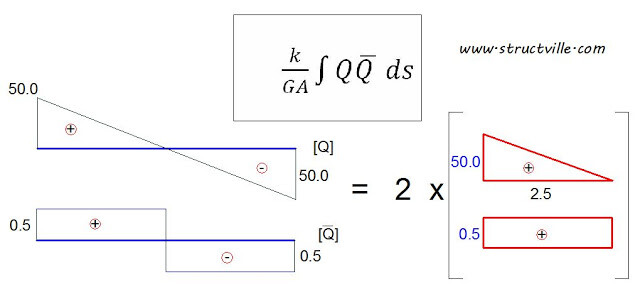


Where does the 1/2 come from in the last example for the deflection due to shear?
And what for cantilever beam subjected to point load at free end
The same procedure adopted for the other systems should work for it also.
And what for a cantilever subjected to a point load at the center of the span
Shear force diagram for the cantilever beam will not be rectangular but triangular.
Shear deformation calculations be corrected.
Thank you very much for that great observation. The anomaly in the diagram has been corrected. The answer remains the same because the calculation was done using the correct triangular diagram.
Nice, mate. Does the maximum deformation happen in the center of the beam?