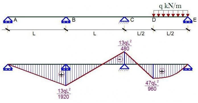
For the continuous beam loaded as shown above, it is desired to find the bending moments at the critical points using force method (method of consistent deformations) and Clapeyron’s theorem (3 Moment Equation). We should however note that both methods are force methods (flexibility method) since we generally solve for unknown forces.
(1) By force method
Degree of static indeterminacy neglecting horizontal forces and reactions.
D = 2m + r – 2n
D = 2(3) + 4 – 2(4) = 2
Therefore the structure is indeterminate to the 2nd order.
Basic System
A basic system is a system that is statically determinate and stable. This obtained by removing the redundant supports at A and B, and replacing them with unit loads. See the figure below.
Case 1
Case 2
Bending moment on the basic system due to unit virtual load at support B
Case 3
Bending moment due to externally applied load on the basic system;
Influence Co-efficients
δ11
δ22
δ11 = [1/6 × L × L(4L + L)] + [1/3 × L × L × L] = 3L3/2
δ1P = [1/6 × qL2/16 × (2L + 2L) × L/2]] + [15/12 × qL2/16 × L × L/2] = 13qL4/384
δ2P
δ2P = [1/6 × qL2/16 × (L + L) × L/2] + [15/12 × qL2/16 × L/2× L/2] = 13qL4/768
The appropriate cannonical equation is given by;
δ11X1 + δ12X2 + δ1P = 0
δ21X1 + δ22X2 + δ2P = 0
Therefore;
(4L3)X1 + (3L3/2)X2 = -13qL4/384
(3L3/2)X1 + (2L3/3)X2 = -13qL4/768
On sloving the above equations simultaneously;
X1 = 13qL/1920 KN
X2 = -13qL/320 KN
The final moment values can now be computed;
Mf = M1X1 + M2X2 + MP
MB = (13qL/1920 × L) + 0 + 0 = 13qL2/1920
MC = (13qL/1920 × 2L) – (13qL/230 × L) + 0 = -13qL2/480
MD = (13qL/1920 × L) – (13qL/230 × L/2) + qL2/16 = 47qL2/960
(2) By Clapeyron’s Theorem;
First of all, we draw the free bending moment diagram
By Clapeyron’s three moment equation (EI = constant, no sinking of support);
MAL1 + 2MB + MCL2 + 6A1X1 + 6A2X2 = 0
Geometrical Properties of the free moment diagram (centroid)
SPAN A – C
MA = 0
2MB(L + L) + MCL = 0
4MB L + MCL = 0 ——————– (1)
SPAN B-D
MD = 0
MBL + 2MC(L + L) = [-6 × 7qL3/192 × 13L/128]/L
MB L + 4MCL = -13qL3/128 ——————– (2)
Solving (1) and (2) simultaneously;
MB = 13qL2/1920
MC = -13qL2/480


• Hello! Someone in my Myspace group shared this site with us so I came to take a look. I’m definitely loving the information. I’m book-marking and will be tweeting this to my followers! Exceptional blog and superb style and design. BIM Solutions in India
BIM Project Management in India
BIM Implementation in India