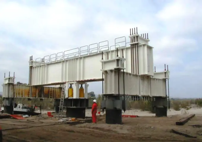
Pile load test is the most reliable method of estimating the load carrying capacity of a pile, but it is rather expensive. Load tests are performed on-site on test piles to verify the design capacity of the piles. A pile load test consists of applying increments of static load to a test pile and measuring the settlement of the pile. The load is usually jacked onto the pile using either large dead weight or a beam connected to uplifts anchor piles to supply reaction for the jack. Load tests could be by constant rate of penetration test (CRP) or maintained load Test (ML).
In arriving at the ultimate load of a pile from pile load test, several definitions of failure have been given some of which are as follows;
(1) Terzaghi (1942) says that a failure load is that which causes a settlement equal to 10% of the pile diameter.
(2) The CP 2004 defines failure load as that load at which the rate of settlement continues undiminished without further increase increment of load unless this rate is so slow as to indicate that this settlement may be due to consolidation of the soil. This definition is a bit difficult to apply in practice especially in cohesive soils.
(3) German DIN 4026 defines failure load as that load which causes irreversible settlement at the pile head equal to 2.5% of the pile diameter.
Design Example
It is desired to estimate the number of piles in a group of piles to carry the following loads;
Permanent load Gk = 3600 KN
Variable Load Qk = 1740 KN
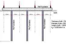
Pile load test has been carried out on 3 piles on the site and the result is as shown below. The piles are 750mm diameter and 15m long. Assume settlement of 10% of the pile diameter as failure criterion.
(1)The ultimate resistance of the pile is the load at settlement of 10% of the pile diameter.
Settlement = 750 × (10/100) = 75mm
(2) From the load settlement graph for each pile;
Pile 1 Rm = 4156.25 KN
Pile 2 Rm = 4318.325 KN
Pile 3 Rm = 4887.8 KN
(3) The mean and minimum measured pile resistances are;
Rm,mean = 4454.125 KN
Rm,min = 4156.25 KN
Read also….
Durability of structures and how to calculate concrete cover
Analysis of Internal Forces in Frames Due to Settlement of Support (with free downloadable PDF file)
(4) The characteristic pile resistance is obtained by dividing the mean and minimum measured pile resistances by the correlation factors ξ1 and ξ2 and choosing the minimum value. The equation below is given by equation 7.2 of Eurocode 7.
For 3 number of test piles (Table A9, EC7);
ξ1 = 1.20
ξ1 = 1.05
Rc,k = min{4454.125/1.2 , 4156.25/1.05} = 3711.77 KN
Combinations of sets of partial factors
DA1.C1 —– A1 + M1 + R1
DA1.C2 ——- A2 + M1 or M2 + R4
Partial factors for actions;
A1 γG = 1.35 γQ = 1.5
A2 γG = 1.0 γQ = 1.30
Partial factors for materials
M1 and M2 not relevant (γϕ’ = 1.0, not used)
Partial Resistance factors
R1 γt = 1.15 (Total/combined compression)
R4 γt = 1.5
DA1.C1 Fc,d = 1.35Gk + 1.5Qk = (1.35 × 3600) + (1.5 × 1740) = 7470 KN
DA1.C2 Fc,d = 1.0Gk + 1.3Qk = (1.0 × 3600) + (1.3 × 1740) = 5862 KN
For a single pile;
DA1.C1 Rc,d = Rc,k/γt = 3711.77/1.15 = 3227.62 KN
DA1.C2 Rc,d = Rc,k/γt = 3711.77/1.5 = 2474.513 KN
Assuming no pile group effect, for n piles,
Resistance = n × Rc,d
Hence,
DA1.C1 n ≥ Fc,d/Rc,d = 7470/3227.62 = 2.31
DA1.C2 n ≥ Fc,d/Rc,d = 5862/2474.513 = 2.36
Therefore, DA1.C2 controls, and 3 number of piles will be required.
Therefore
Rc,d = 3 × 2474.513 = 7423.539
Fc,d = 5862 KN
Fc,d/Rc,d = 5862/7423.539 = 0.789 < 1.0 Ok
Combinations of sets of partial factors
DA2 —– A1 + M1 + R2
Partial factors for actions;
A1 γG = 1.35 γQ = 1.5
Partial factors for materials
M1 not relevant (γϕ’ = 1.0, not used)
Partial Resistance factors
R2 γt = 1.1 (Total/combined compression)
Fc,d = 1.35Gk + 1.5Qk = (1.35 × 3600) + (1.5 × 1740) = 7470 KN
For a single pile;
Rc,d = Rc,k/γt = 3711.77/1.1 = 3374.336 KN
Assuming no pile group effect, for n piles,
Resistance = n × Rc,d
Hence,
n ≥ Fc,d/Rc,d = 7470/3374.336 = 2.21
Therefore number of piles required = 3 piles
Combinations of sets of partial factors
DA3 —– A1 + M1 + R3
Partial Resistance factors
R3 γt = 1.0 (Total/combined compression)
Since the R3 recommended partial resistance factor is 1.0, there is no margin for safety on the resistance provided. Therefore this cannot be used for the design.
3 Number of 750mm diameter piles is suitable for the load at ultimate limit state.
Thank you for visiting Structville today, and we will look at other aspects of pile design in our subsequent posts.
Meanwhile, have you read…
Solved example on elastic settlement of shallow foundations
Interact with our facebook community at;
www.structville.com/structville


Great Article
Cyber Security Projects for CSE Students
JavaScript Training in Chennai
Project Centers in Chennai
JavaScript Training in Chennai
Thank you so much for sharing this valuable information! It’s really helpful and insightful. I appreciate the effort you’ve put into explaining things so clearly. Looking forward to reading more of your posts!