Settlement of foundations can occur due to loads from the superstructure of buildings. Geotechnical engineers are usually interested in seeing that the settlements are uniform and limited to a certain depth. In some cases however, it is anticipated that differential settlement may occur.
Example
Let us consider a 6m cantilever that is supported on a roller at the free end. The roller support undergoes a vertical settlement of 25mm (downwards). We are to determine the additional bending moment at the fixed support due to the settlement. We will approach this problem using force and stiffness methods.
Solution
(a) By force method
A propped cantilever (roller support) is indeterminate to the 1st order. The adopted basic system for the structure is a simple 6m cantilever. We will now replace the redundant vertical reaction with a unit load, and the resulting bending moment diagram is as shown below.
The appropriate cannonical equation is given by;
δ11X1 + δ1∆ = 0
Where;
δ11 = Deformation at point 1 (free end) due to unit load at point 1
δ1∆ = Deformation at point 1, due to settlement of Support = – EI(∆.S)
δ11 = (1/3) × 6 × 6 × 6 = 72
On the other hand;
δ1∆ = – EI(∆.S) = -22500 (1 × -0.025) = 562.5
Substituting into the canonical equation and solving;
72X1 + 562.5 = 0
On solving;
X1 = – 7.8125 kN (downward reaction)
With this reaction now known, the moment at support A due to the sinking of support;
MA = – 7.8125 × 6 = -46.875 kNm (hogging moment)
(b) By stiffness method
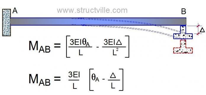
With support A fully fixed and support B simply supported, the general equation for bending moment at support A due to external load and settlement of support is given by;
MAB = [(3EIθA/L) – (3EI∆/L2)] + FAB
Where FAB is the fixed end moment due to externally applied load = 0
Also θA = 0 since support A is fully fixed.
∆ = 25mm = -0.025m (negative due to downward settlement).
MAB = [((3 × 22500)/6) × (-0.025/6)] = -46.875 kNm
Now, we obtained the answer above expressly because of very known facts. Since the bending moment at B zero, we may not pass through the stress of obtaining the rotation at support B. However for the sake of knowledge, let us apply a more general method which a lot of people might be more familiar with. Here, we will obtain the rotation (slope) at support B, and use it to obtain the bending moment at support A. We are initially assuming that all supports are fixed in the development of the slope deflection equations.
MAB = EI/L[(4θA + 2θB – 6∆/L)] + FAB
MBA = EI/L[(2θA + 4θB – 6∆/L)] + FBA
For equilibrium and compatibility;
MBA = 0
We also know that θA = 0 (fixed support), and there is no external load being considered;
22500/6[4θB – (6 × -0.025)/6] = 0
15000θB + 93.75 = 0
Therefore, θB = -0.00625 radians
Substituting the value of θB into the slope deflection equation for MAB
MAB = EI/L[(2θB ]
MAB = 3750[(2 × -0.00625)] = 46.875 kNm
Thank you for reading to the end.


Great work obinna ranks. More grace to u.
Thank you so much Ovie
Thank you so much
I'm not a creative person, but I'm good at following directions, so thanks for sharing your creative talent with others. It's inspirational!bim services
bim servicesin USA
bim servicesin Uk
You’re very insightful Engineer. I pick my refreshers always from your web. Be blessed for sharing the knowledge