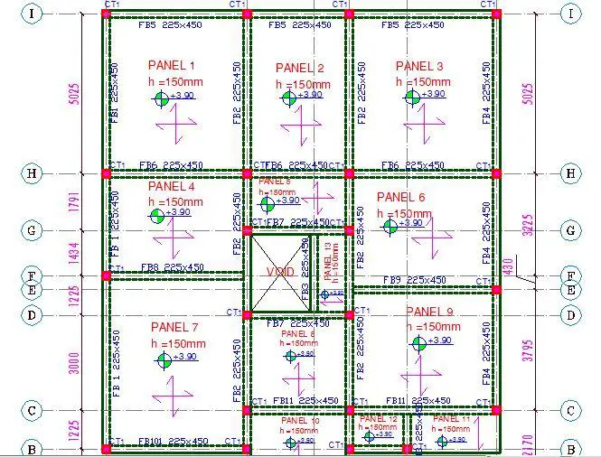
The general arrangement (GA) or structural layout is a drawing that clearly specifies the disposition of the structural elements in a building such as the columns, beams, panelling of the floor slabs etc, on which the design of the structure is based. By looking at the GA of a building, other engineers can identify the model of the building, the shape and type of structural elements, and the possible assumptions made in the design.
In order to carry out a design properly, the design engineer should be able to adequately idealise the structure in order to obtain the closest theoretical and practical behaviour of the structure under load. This interpretation is usually made from standard and well-prepared architectural drawings of the proposed building.
The architectural drawings enable the engineer to prepare what is normally referred to as the ‘general arrangement’ of the building, popularly called the ‘GA’ or the ‘Structural Layout’. The GA also contains the labelling of the axes and members, unique grid lines, building structural levels, etc. After completing the general arrangement drawing, the engineer makes preliminary sizing of the structural elements which may be governed by past experience or by deflection requirements based on the code of practice. After the sizing, the engineer is faced with the challenge of loading the structure. But let us briefly review how we go about the GA.

General Ideas on the Preparation of General Arrangement (GA)
There are no hard and fast rules on how to select the appropriate general arrangement of a structure. To the best of our knowledge, adequate presentation of the general arrangement drawing has more to do with the years of design and construction experience.
However, let us highlight some important guidelines which are very necessary.
(1) Respect the architect’s original disposition:
In the preparation of a general arrangement drawing, try as much as possible to respect the architect’s design. Architectural drawings supersede structural drawings for building projects, therefore, the structural drawing must conform to the architectural drawing – not the other way around.
For instance, when arranging your columns, do not place columns where the architect desires a free/uninterrupted space, no matter how well the column placement will positively affect the structural behaviour. By implication, none of your structural elements should interrupt the interaction of spaces. In addition to that, your columns and beams should not project out or drop where the architect has intended plain walls or flush ceilings, etc. Your arrangement of the structural elements should be consistent with the original form of the building.
(2) Select a stable model:
The model or general arrangement you are adopting should be statically stable, and fully representative of the behaviour of the structure. There should be no stability or equilibrium problem at any joint or location in the building.
(3) Clearly define the load path
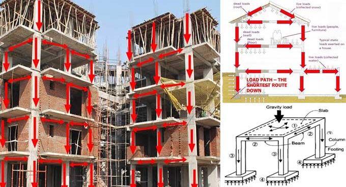
The load path is the way through which loads of the building travel through the connected parts of the structure before being transmitted to the foundation. In a conventional building, the load path is normally from the floor slab to the beams, then to the columns, and finally to the foundations. All special situations such as the use of tension columns or transfer structures should be carefully planned out.

(4) Consider buildability and construction consequences:
The structural model adopted should be buildable. This starts by considering the technical capacities of the contractors who will execute the design from your model. For instance, in a region where reinforcement bending machines and cranes are not readily available, you should not provide models and structural arrangements that will require the provision of high-yield 32mm reinforcement bars, or recommend the use of precast or prestressed elements. This comes in handy by preventing very large spans as practically as possible.
Every construction project has a budget, and your designs should reflect that. For instance, it is very normal to limit the sizes of the reinforcement bars to a maximum of 16mm for simple residential duplex design, unless the building model cannot help it. This can be achieved by moderating the span of the structural elements, knowing full well that the live load in residential buildings are not so heavy.
(5) Know the economic and structural consequences of your arrangement:
Between more steel reinforcements and more concrete, which one is more economical in the region? For instance, let us consider an external beam that should have been 8m long under simply supported assumptions. If there are no openings at the wall panels under the mid-span of the beam, you can comfortably hide an intermediate column there, thereby having two spans of 4m each.
The original 8m beam span would have required more steel reinforcements, deeper sections, or both to satisfy ultimate and serviceability limit state requirements. However, if you introduce a column at the mid-span, there will be a redistribution of stresses, with a hogging moment at the propped mid-span, and hence, generally lesser reinforcements, concrete section, and deflection.
However, you should note that you are now going to construct a new column and new isolated base (requiring concrete, reinforcement, and additional excavation cost). Between the two options, which one gave you the most economical solution? Is the cost of constructing a foundation in that area cheap or expensive? Are there groundwater problems, etc? These are all influencing factors, and as highlighted earlier, years of design experience counts.
Case Study on General Arrangement Drawing Preparation
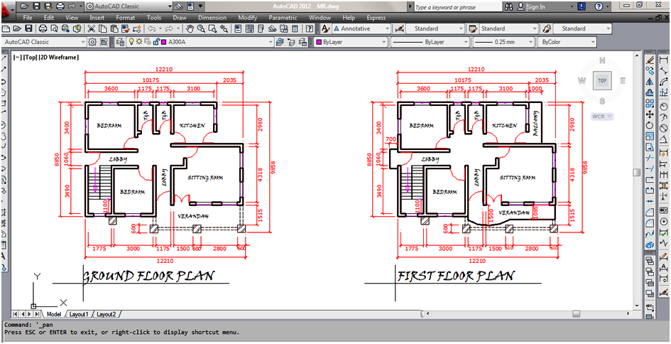
In this article, a small residential building on a 10m x 15m plot of land has been presented for the purpose of preparing the structural general arrangement. The ground and first-floor plans of the building are shown in the figures below. From the architectural disposition, the building is a two-family occupancy arrangement, with each family occupying a floor level. The 1st floor of the building has a balcony in the kitchen area, a cantilever sit-out, and a little balcony by the staircase area. Apart from that, the general arrangement is fairly the same.
How to prepare the general arrangement of a building
The architectural drawing of a building can come to a structural engineer in many formats such as hard copy or soft copy (pdf or cad drawing) or both. If it comes as a soft copy of a CAD drawing, then the work is made easier and more accurate. If it comes as a hard copy, then kindly request a soft copy, otherwise, you will have a lengthier job to do.
So let us quickly run down through Structville’s style of preparing the general arrangement drawing of a building, when the drawing comes in AUTOCAD format.
(1) It is advisable to place the ground floor plan side by side with the floor plans of the subsequent storeys on the graphical user interface window of your AUTOCAD (see Figure below).
Note that architectural drawings come with their own unique grid lines. In the building we are trying to design here, some details (like gridlines) have been removed from the architectural drawing for the purpose of clarity of very necessary details like dimension lines. After placing the floor plans side by side on the window, you can start noticing a few different things about the floor plans immediately. For ease of construction setting out, it is important that the architectural and structural drawings have consistent gridline labels.
(2) Copy the floor plans to another location on the window (still leaving the ones you placed side by side for quick reference).
(3) Copy the plan of the first floor, and paste it on the ground floor plan, so that the dimensions and axes are matching perfectly. Just like I hinted earlier, grid lines are unique. Grid line (axis) A-A on the ground floor still represents axis A-A on the 4th floor whether they contain the same elements or not.
HINT: You should choose a prominent corner of the building as a pick-up point for your copy-and-paste operation (this is to make your axis match more properly). For more clarity, you can change the colour or thickness (or both) of the ground-floor elements and first-floor elements and gridlines, so that you can rightly distinguish between the two, but do not mess with the drawing layers on your AUTOCAD during this process.
(4) After you have superimposed the first floor on the ground floor, you should see the interaction between the two floors. All axes with elements that are coincidental should be visible, and all axes with members that are not coincidental should also become visible.
HINT: Architectural drawings can be clouded with lots of details that are not important to a structural engineer. To help you see more clearly and make your decisions faster, you can turn off the layers of irrelevant details such as furniture, sanitary fittings, etc as appropriate. Whenever you get confused, look at the sections of the building for more information, and when the details provided are still not clear, you can contact the architect for more clarification.
At this point, you can also see the outline of blockwork on the first floor, and this can be more critical for the general arrangement of the first-floor slab. It will properly guide you on the selection of the floor beam axis. Engineers usually prefer to have their major block works sit directly on beams unless they cannot help it. This is to prevent major block wall loads from sitting directly on slab panels (note that this can be designed for)
On the other hand, the blockwork axis of the ground floor will aid you in the design of the foundation layout, especially for the strips. Do not work on the ground floor alone without looking at the first floor – the last thing you will want to happen is to place a column somewhere on the ground floor, and helplessly see it popping out through the lobby of the first floor (unless the column will be terminated at the first floor).
So carefully make your selections based on matching axes, and fair uniformity. And as hinted earlier, your arrangement must be consistent with what the architect has in mind. So this is much like art, and you have to use your ingenuity here.
“My supervisor during my industrial training once told me that preparation of structural layout is the MAJOR WORK to do in structural design. Five engineers can prepare the GENERAL ARRANGEMENT of a building using the same drawing, and come up with five different layouts that are plausible. But WHEN EVALUATED critically, some solutions may be better than the others.”
(5) After studying the two floors, the next thing to do is to create a rectangular or square box (say 230 x 230mm) on AUTOCAD, and hatch it with any pattern appealing to you (I normally use SOLID). This represents your columns on the floor plan. Now carefully copy this element and start pasting it at the locations where you have decided to place your columns (this usually occurs at intersections between axes). Personally, I normally start at the corners of the building because more often than not, columns must be there irrespective of the arrangement. After that, you can move to the interiors and place your columns as desired.
(6) After you are satisfied with what you have done, carefully check the interaction of the arrangement, and make sure that they are reasonable. At this point, you can start seeing how your floor beams will connect. Areas, where primary and secondary beams will interact, will now become visible, and this is another stage of critical thinking to see if there are better solutions and alternatives.
Once you connect your floor beams as appropriate, the general arrangement drawing work is basically done. You can now ‘fine tune’ it, and add other relevant details.
Sample thought process in general arrangement creation
To make some points clearer, let us look at a portion of the plan we are considering in this text (see figure below).
We wish to place columns along gridline A.
A little consideration will show that we can place columns at points A1, A3, and A5. Also, we can alternatively place columns at points A1, A2, A4, and A5. Without reading further, ponder on that arrangement and see the alternative that you will prefer.
If I should choose to place a column at points A1, A3, , and A5 (neglecting A2 and A4), these are some of the implications;
(1) I will have a larger span for A:1-3 and A:3-5. But note that the spans are considerably moderate for such RC structure in our case study.
(2) I will have a floor beam running along gridline 3 (the beam will probably have to run down to gridline B or C before encountering another support.
(3) I may need to have secondary beams along gridlines 2 and 4 to support the wall load above.
(4) If I ignore the use of secondary beams along gridlines 2 and 4, the floor slabs on the bedroom and kitchen will be subjected to block wall load from the walls on axis 2 and 4 which must be designed for.
If I should choose the second alternative (placing columns at points A1, A2, A4, and A5);
(1) I will have shorter spans and of course there will be three spans instead of two. The bending moment on Span A:2 – 4 will probably be hogging due to its short span relative to others.
(2) I will have a wall along axis 3, but by proximity and considering load sharing implication, it will not be critical, and will not affect my designs like the previous alternative.
(3) My floor beam at axis 2 will stop at axis B, and my floor beam at axis 4 will stop at the wall close to axis B. So I will not have a complex arrangement to deal with.
Considering all these consequences, I preferred the second alternative. I feel it gives the building more robustness.
However, if the building is to be located in an area where the soil is so bad that constructing foundations will be very expensive, we can settle for alternative 1 since we want as fewer foundation points as possible. The final GA I adopted for the whole model is shown in the figure below.
However, if the drawing comes in form of a paper work, then nothing changes in the approach. Place the floor plans side by side, and manually make your decisions as highlighted above, before you go into drafting.
To download this post as a PDF file, click HERE
I will be dropping my pen here guys. Note that this post is an excerpt from my highly interactive design book called ‘Structural Analysis and Design of Residential Buildings using Staad Pro, CSC Orion, and Manual Calculations’


how much is the book
Thank your for such a nice article
Thank you sir,really appreciate you .
Thank you for this knowledge. It is really helpful. Thank you once again.
In any case, on the off chance that you know the procedures, it ought not be that difficult.
Great Blog… The information you shared is very effective for learners I have got some important suggestions from it, Keep Sharing such a nice blog.
Nice Content Thanks for sharing ..
I have read your blog it is very helpful for me. I want to say thanks to you. I have bookmark your site for future updates.
In order to carry out a design properly, the design engineer should be able to adequately idealise the structure in order to obtain the closest theoretical and practical behaviour of the structure under load.
This article has expressed the best way of preparing general arrangement drawing in a very short but clear way, so succinct.
This is a good one from an experienced personnel. However, there are cases, where the ground floor plan is entirely different from the first floor plan, with almost all internal columns terminating just below the first floor. Meaning new columns would be erected from the first floor to bear the roof beams. Can you please shed some lights on this area. Especially where the first floor is cantilevered on the three sides of the building typical of a job I am currently working on. Anticipating your response, thanks.
good day boss, i was just about asking the same thing before i saw your response.
please how were u able to go about it, having different grd plan and first floor plan
Nice one UBANI OBINNA ON your book, can i get the book above from bookshops, am a graduate of civil engineering and with basic knowledge on using orion software, i based in Jos plateau state.
Greetings, they are not available in bookshops.
Thanks for the indept revelation you’ve brought our way via this blog, but please I’ll beckon u look into Michaels case, I’m having issues in that aspect too
Greetings,
We provide accurate material take-offs and cost estimates on reasonable cost and with short turnaround. Our team of professionals has been providing these services to Home builders, Tenders/Extensions, Garage and loft conversion. We have more than 17 years of experience in estimating services. We are giving almost 25% discounts on the first estimate. Just send us plans/ drawings to get the free proposal quote for charges and turnaround. Also let me know if you need our work samples. Thanks
Very helpful article I recommend it to all civil engineering graduates.