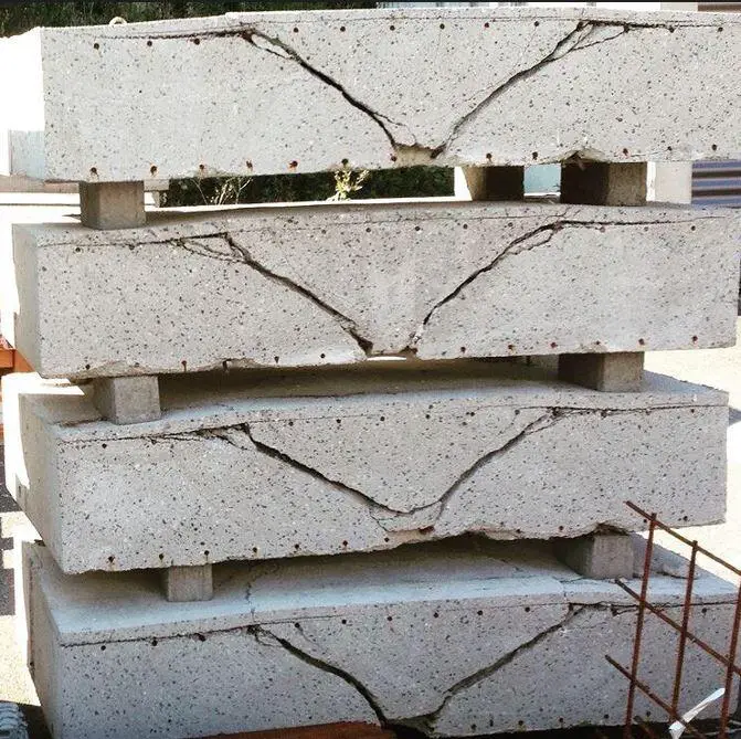
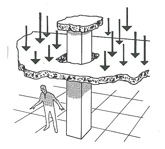
Punching shear failure occurs in a slab when the magnitude of a concentrated load (such as that from a column) exceeds the shear strength or resistance of the slab or the column punches through the slab. The failure plane is located at a certain distance from the perimeter of the column and has a funnel-shaped failure pattern. The design for punching shear resistance in flat slabs normally involves controlling the thickness of the slab or providing punching shear reinforcement.
Generically, punching is a three-dimensional, brittle failure mechanism leading to a truncated cone that separates from the slab. The shear crack develops from tangential flexural cracks and propagates into the direction of the compression zone near the column edge constricting the circumferential compression ring with increasing loads. Once the punching shear resistance is reached the shear crack intersects the uncracked compression ring leading to a sudden penetration of the column into the slab.

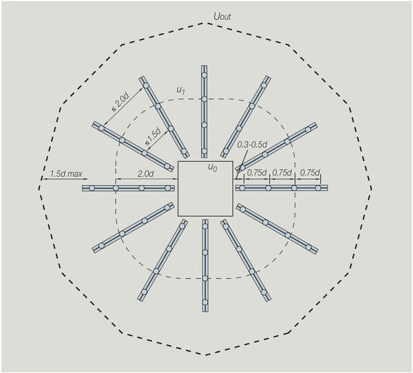
The recommendations found in BS EN 1992 (Eurocode 2) are usually followed when designing punched shear reinforcement. To assess whether punched shear reinforcement is necessary, the shear stress in the concrete is computed at the column face and at the fundamental control perimeter u1 (2d from the column face).
The position of the outside control perimeter where shear reinforcement is no longer needed (uout) is then determined if reinforcement is necessary. Shear studs are placed starting at 0.3d or 0.5d from the column face to within 1.5d of the outer control perimeter (uout), with intermediate studs spaced at 0.75d intervals.
The most cost-effective approach will often be a radial arrangement, with rails spaced either 30° or 45° apart. To meet this requirement, extra secondary rails are installed as necessary. The tangential spacing between studs is kept to within 1.5d for studs inside the basic control perimeter (u1) and 2d for studs outside the basic control perimeter.
The suggested values from BS EN 1992 can be used to design shear load VEd for internal, edge, and corner columns where lateral stability does not depend on frame action between slabs and columns and where neighbouring spans differ by less than 25%.
Design for punching shear should take moment transfer into account at the intersection of the column and slab. The design punching shear can be obtained for structures whose lateral stability is not dependent on the frame action between the slab and columns and where adjacent spans do not differ in length by more than 25% by increasing VEd by 1.15 for internal columns, 1.4 for edge columns, and 1.5 for corner columns.

Generally, the following checks should be carried out:
- Ensure that maximum punching shear stress is not exceeded, i.e. vEd < vRd,max at the column perimeter
- Determine whether punching shear reinforcement is required, i.e. whether vEd > vRd,c at the basic perimeter, u1
- Determine whether punching shear reinforcement is required, i.e. whether vEd > vRd,c at at successive perimeters to establish uout = the length of the perimeter where vEd = vRd,c. Perimeters within 1.5 d from uout need to be reinforced.
Where required provide reinforcement such that vEd ≤ vRd,cs.
where
vEd = applied shear stress. The shear force used in the verification should be the effective force taking into account any bending moment transferred into the slab (see above)
vRd,max = design value of the maximum punching shear resistance, expressed as a stress
vRd,c = design value of punching shear resistance of a slab without punching shear reinforcement, expressed as a stress
vRd,cs = design value of punching shear resistance of a slab with punching shear reinforcement, expressed as a stress.
vRd,cs = 0.75 vRd,c + 1.5 (d/sr)Asw fywd,ef (1/u1d)sin a
where:
Asw = area of shear reinforcement in one perimeter around the column (subject to Asw,min)
sr = radial spacing of perimeters of shear reinforcement
fywd,ef = effective design strength of reinforcement (250 + 0.25d) ≤ fywd
d = mean effective depth in the two orthogonal directions (in mm)
u1 = basic control perimeter at 2d from the loaded area
sin a = 1.0 for vertical shear reinforcement
Where required each perimeter should have
Asw = (vEd – 0.75 vRd,c)sr u1/(1.5 fywd,ef)
The punching shear resistance of a slab should be assessed for the basic control section (see Figure 6.12). The design punching shear resistance [MPa] may be calculated as follows:
vRd,c = CRd,c k (100 ρl fck)1/3 + k1 σcp ≥ (vmin + k1 σcp)
where:
fck is the characteristic compressive strength of concrete, see Table 3.1
k= 1 + √200/d ≤ 2.0
where d is the effective depth, in [mm]ρl= (ρly⋅ρlz)1/2 ≤ 2%
ρly, ρlz are longitudinal reinforcement ratios in y- and z- directions respectively. Their values should be calculated as mean values taking into account a slab width equal to column width plus 3d each side σcp= (σcy + σcz)/2,
where σcy, σcz are the normal concrete stresses in the critical section in y- and z- directions (in [MPa], positive if compression):
σcy = NEd,y / Acy and σcy = NEd,z / Acz
NEd,y, NEd,y are the longitudinal forces across the full bay for internal columns and the longitudinal force across the control section for edge columns. The force may be from a load or prestressing action.
Acy, Acz are the areas of concrete according to the definition of NEd,y, NEd,y respectively
CRd,c is a Nationally Determined Parameter, see § 6.4.4 (1)
vminis a Nationally Determined Parameter, see § 6.4.4 (1), or (6.3N) for the calculation of vmin following the Eurocode recommendation
k1 is a Nationally Determined Parameter, see § 6.4.4 (1).
Punching Shear Design Example
For the flat slab with the general arrangement as shown below, let us design the punching shear for column B1 given the following design information;
Ultimate axial force on column VEd = 400 kN
Thickness of slab = 250 mm
Dimension of column = 450 x 230 mm
Reinforcement of slab in the longer direction = H16@150mm (As,prov = 1340 mm2)
Reinforcement of slab in the shorter direction = H16@175mm (As,prov = 1149 mm2)
Grade of concrete = C30
Yield strength of reinforcement = 500 Mpa
Concrete cover to slab = 25mm
Solution
Effective depth of slab in y-direction dy = 250 – 25 – (16/2) = 217 mm
Effective depth of slab in x-direction dx = 250 – 25 – 16 = 209 mm
ρly = (1340) / (1000 × 217) = 0.00617 (reinforcement ratio)
ρlx = (1149) / (1000 × 209) = 0.00549 (reinforcement ratio)
(a) Check shear at the perimeter of the column
VEd = β VEd/(u0d) < VRd,max
From figure 6.21N of EN 1992-1-1;
β = 1.40
d = (217 + 209)/2 = 213 mm
u0 = c2 + 3d < c2 + 2c1 For edge columns (clause 6.4.5(3))
u0 = 230 + (3 × 213) < (230 + 2 × 450)
u0 = 869 mm
VEd = 1.40 × 400 × 1000/(869 × 213) = 3.025 MPa
VRd,max = 0.5 ν fcd
= 0.5 × 0.6(1 – fck/250) × αcc fck/γm
= 0.5 × 0.6(1 – 30/250) × 1.0 × (30 /1.5) = 5.28 MPa
VEd < VRd,max …OK
(b) Check shear at u1, the basic control perimeter
VEd = β VEd/(u1d) < VRd,c
β,VEd as before
u1 = c2 + 2c1 + π × 2d
u1 = 230 + (2 × 450) + (π × 2 × 213) = 2468 mm
VEd = 1.4 × 400 × 1000/(2468 × 213) = 1.065 MPa
VRd,c = 0.12 k(100 ρl fck)1/3
k = 1 + (200/d)1/2 = 1 + (200/213)1/2 = 1.969
ρl = (ρlyρlx)1/2 = (0.00617 × 0.00549)1/2 = 0.00582
VRd,c = 0.12 × 1.969(100 × 0.00582 × 30)1/3 = 0.613 MPa
VEd > VRd,c ?
1.065 MPa > 0.613 MPa … Therefore punching shear reinforcement required
NA check:
VEd ≤ 2.0VRd,c at basic control perimeter
1.06 MPa ≤ 2 × 0.613 MPa = 1.226 MPa – OK
(c) Perimeter at which punching shear no longer required
uout = β VEd/(dVRd,c)
= 1.4 × 400 × 1000/(213 × 0.613) = 4289 mm
Rearrange: uout = c2 + 2c1 + π rout
rout = (uout – (c2 + 2c1))/π
rout = (4289 – 1130)/π = 1005 mm
Position of outer perimeter of reinforcement from column face:
r = 1005 – 1.5 × 213 = 686 mm
Maximum radial spacing of reinforcement:
sr,max = 0.75 × 213 = 159.75 mm, say 150 mm
(d) Area of reinforcement
Asw ≥ (VEd – 0.75VRd,c)sru1/(1.5fywd,ef)
fywd,ef = (250 + 0.25d) = 303 MPa
Asw ≥ (1.065 – 0.75 × 0.613) × 150 × 2468/(1.5 × 303)
≥ 492 mm2 per perimeter
Provide 7H10 (Asprov = 549 mm2 per perimeter)
Within the u1 perimeter the link spacing around a perimeter,
st ≤ 1.5d = 1.5 × 213 = 319.5 mm
Outside the u1 perimeter the link spacing around a perimeter,
st ≤ 2d = 426 mm
Use say st,max = 300 mm
Minimum area of a link leg:
Asw,min ≥ [0.053 sr st sqrt(fck)] /fyk = (0.053 × 150 × 300 × √30) / 500
≥ 26 mm2
Use H10s (78.5 mm2) and 7 per perimeter.
@ 300 mm tangential spacing and @150 mm radial spacing

Thank you for visiting Structville today and God bless you.


Keep up this great work Bro. Thanks alot
Hi.. it would be nice sir to do a sketch of the punching shear rebar arrangement. So as aid me in understanding the example well.. Cheers
Thank you for this detailed example. Keep going.
• One thing that always troubled me was that even with the net, most people still don’t tend to address about the topic in this quality.
bim services
bim servicesin USA
bim servicesin Uk
https://drawings.archicgi.com/
Thank you.
I love your vast knowledge and how you help with it. I will like you to talk about pile supporting lift wall
It’s perfectly crystal clear! thanks a lot
In example, are you using slab top or bottom reinforcement (B16-150 & B16-175) ?
Hi
I think ”dx” must be replaced.
The correct calculation is:
dx=250-25-16-(16/2)=201 mm
So there is some variation in the rest of the calculations.