Welded connections are one of the most fundamental and versatile methods for joining steel members in structural applications. Their inherent strength, reliability, and cost-effectiveness make them a popular choice across various industries, from building construction and bridges to shipbuilding and machinery.
However, ensuring the safety and efficiency of these connections requires careful design and adherence to established codes of practice. In this article, we review the design of welded connections, exploring their key design principles, common types, and considerations, with Eurocode 3 (EN 1993) serving as our primary reference for best practices.
Fundamental Principles of Welded Connections
At the heart of welded connection design lies the understanding of stress distribution and material behaviour. Welds introduce inherent discontinuities within the structure, potentially creating stress concentrations. Therefore, selecting the appropriate weld type, size, and location becomes crucial. Eurocode 3 provides detailed guidance on various weld types, such as butt welds, fillet welds, and groove welds, each with its own load-carrying capacity and suitability for specific scenarios.
Material Properties
Understanding the base metal and filler metal properties is equally important. Eurocode 3 classifies different steel grades based on their yield strength, ultimate tensile strength, and ductility. The chosen weld metal must be compatible with the base metal, ensuring adequate strength and avoiding excessive brittleness.
Load Analysis and Design Methods
Accurately determining the loads acting on the connection is paramount. Eurocode 3 outlines various load combinations including dead loads, imposed loads, wind loads, and seismic loads. Once the loads are defined, different design methods can be employed, such as the ultimate limit state (ULS) and the serviceability limit state (SLS). The ULS ensures sufficient strength to prevent weld failure, while the SLS addresses factors like excessive deformations and fatigue resistance.
Common Types of Welded Connections
- Butt Welds: Join two members along their full cross-section, often used for plates and pipes.
- Fillet Welds: Connect two members at an angle, suitable for various member combinations.
- Groove Welds: Similar to butt welds, but with a prepared groove in one or both members for greater weld penetration.
- Tee and Corner Joints: Connect members forming an L or T shape, requiring careful consideration of stress concentrations.
Eurocode 3 Requirements
Eurocode 3 provides comprehensive design rules and guidance for welded connections. Key aspects include:
- Weld throat thickness: Defines the effective depth of the weld, crucial for calculating its load-carrying capacity.
- Electrode selection: Specifies suitable electrodes based on material properties and desired weld characteristics.
- Joint geometry: Provides recommendations for joint preparation, weld size, and edge distance to ensure proper stress distribution.
- Fatigue design: Addresses welds subjected to cyclic loading, requiring specific design considerations.
- Fabrication and quality control: Outlines requirements for welding procedures, welder qualifications, and inspection methods.
Additional Considerations
- Residual stresses: Welding introduces residual stresses within the structure, which can affect the overall behavior and need to be accounted for in the design.
- Distortion and shrinkage: The heating and cooling process during welding can cause distortion and shrinkage of the members, requiring measures to control these effects.
- Fatigue resistance: Connections experiencing repeated loading require careful design for fatigue resistance, potentially involving specific weld details and material selection.
Welded Connection Design Example
In our previous post, we were able to present an example of the design of fillet welds for truss members using two different approaches. In this article, we are going to simplify it further by presenting an example of how the strength of fillet welds can be easily verified, according to the requirements of Eurocode 3.
Solved Example
A 150 mm diameter hollow steel pipe is welded to a plate of thickness 25 mm of grade S275. If the welding side is 12 mm, determine the shear resistance of the welded connection (see the connection example with the picture below).
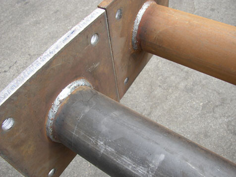
Solution
Steel grade = S275
Thickness of plate (t) = 25 mm < 40 mm, therefore fu = 430 Mpa (Table 3.1 BS EN 1993-1-1)
For steel grade S275, βw = 0.85 (Table 4.1, BS EN 1993-1-1)
The throat of the weld
a = (√2/2) × welding side
a = 0.7071t
a = 0.7071(12) = 8.485 mm
Design weld shear strength
fvwd = (fu/√3)/(βwγm2)
fvwd = (430/√3)/(0.85 × 1.25) = 233.65 Mpa
Weld resistance per length
Fw,Ed = fvwda
Fw,Ed = 233.65 × 8.485 = 1982.58 N/mm = 1.982 kN/mm
Since the weld is done right round the perimeter of the pipe, the weld length L = πd = π × 150 = 471.24 mm
The total weld resistance = Fw,Ed × L = 1.982 × 471.24 = 934 kN
Therefore, the shear force at the base must not exceed 934 kN
Conclusion
Designing welded connections effectively requires a combination of engineering principles, material understanding, and adherence to established codes like Eurocode 3. This comprehensive guide serves as a starting point, highlighting key aspects and considerations. However, for real-world applications, seeking the expertise of qualified engineers and strictly adhering to relevant code provisions remain essential for ensuring safe and reliable structural performance.








The good thing about this TIG welder is that it is proven to be very efficient with thinner gauge materials. Many welding machines fail miserably in that area. It also works well with thick materials. The AHP AlphaTIG 200X can produce thin and precise welds and can handle 1/4" aluminum and 3/8" steel. check out this site
Thank you so much for sharing your informative blog post with .