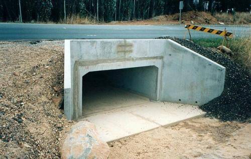
A culvert is a drainage structure designed to convey stormwater or stream of limited flow across a roadway. Culverts can consist of single or multi-span construction, with a minimum interior width of 6 m when the measurement is made horizontally along the centreline of the roadway from face to face of side walls.
Technically, any such structure with a span over 6 m is not a culvert but can be treated as a bridge. Box culverts consist of two horizontal slabs at the top and bottom, and two or more vertical side walls which are built monolithically.
For proper performance of culverts in their design life, there must be a hydraulic design, which will give the geometric dimensions or openings that will convey the design flood. It is typical for culverts to be designed for the peak flow rate of a design storm of acceptable return period.
The peak flow rate may be obtained from a unit hydrograph at the culvert site, or developed from a stream flow and rainfall records for a number of storm events. In the absence of hydraulic data, it is wise to make conservative assumptions based on visual inspection of the site, performance of existing culverts and other drainage infrastructures, or by asking locals questions.
Structural Design of Box Culverts
Structural design begins when the structural design units receive the culvert survey and hydraulic design report from the hydraulics unit. The report in conjunction with the roadway plans shall be used to compute the culvert length, design fill, and other items that lead to the completed culvert plans.
Box culverts are usually analysed as rigid frames, with all corner connections considered rigid and no consideration for side sway. The centreline of slabs, walls and floor are used for computing section properties and for dimensional analysis. Standard fillets which are not required for moment or shear or both shall not be considered in computing section properties.
Design Loads
The structural design of a reinforced concrete box culvert comprises the detailed analysis of a rigid frame for bending moments, shear forces, and axial forces due to various types of loading conditions outlined below:
(i) Permanent Loads
- Dead loads
- Superimposed dead loads
- Horizontal earth pressure
- Hydrostatic pressure and buoyancy
- Differential settlement effects
(ii) Vertical Live Loads
- HA or HB loads on the carriageway (Load Model 1 of Eurocode)
- Footway and Cycle Track Loading
- Accidental Wheel Loading
- Construction Traffic
(iii) Horizontal Live Loads
- Live Load Surcharge
- Traction
- Temperature Effects
- Parapet Collision
- Accidental Skidding
- Centrifugal Load
I believe that these loads are very familiar to designers, otherwise, the reader should consult standard textbooks. However, I am going to point out some important considerations worthy of attention while assessing design loads on culverts.
Loading of Box Culverts to Eurocode 1 Part 2 (EN 1991-2)
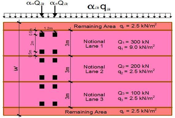
The traffic loads to be applied on box culverts are very similar to those to be applied on bridges. The box culvert will have to be divided into notional lanes as given in Table 1;
| Carriageway width (w) | Number of notional lanes (n) | Width of the notional lane | Width of the notional lane |
| w < 5.4 m | 1 | 3 m | w – 3m |
| 5.4 ≤ w < 6m | 2 | 0.5w | 0 |
| 6m ≤ w | Int(w/3) | 3 m | w – 3n |
The loading of the notional lanes according to Load Model 1 (LM1) is as given in Figure 1;
Concentrated loads
According to BD 31/01, no dispersal of load is necessary if the fill is less than 600 mm thick for HA loading. However, once the fill is thicker than 600 mm, 30 units of HB loads should be used with adequate dispersal of the load through the fill. This same concept can be adopted for LM1 of EN 1991-2.
Earth Pressure
Depending on the site conditions, at rest pressure coefficient ko = 1 – sin (∅) is usually used for analysing earth pressure.
Loading Example
A culvert on a roadway corridor has the parameters given below. The culvert was found at a location with no groundwater problem. Using any suitable means, obtain the design internal forces induced in the members of the culvert due to the anticipated loading conditions when the culvert is empty under the following site conditions:
(1) The top slab of the culvert is in direct contact with the traffic carriageway and overlaid with 75 mm thick asphalt
(2) There is a 1.2 m thick fill on the top of the culvert before the carriageway formation level.
The geometry of the culvert
Total length of culvert = 8 m
Width of culvert c/c of side walls = 2.5 m
Height of culvert c/c of top and bottom slabs = 2.0 m
Length of wing walls = 2.12 m
The thickness of all elements = 300 mm
The thickness of the asphalt layer = 75 mm
Materials property
The angle of internal friction of fill soil = 30°
Unit weight of water = 9.81 kN/m3
Unit weight of backfill soil = 19 kN/m3
Unit weight of concrete = 25 kN/m3
Unit weight of asphalt concrete = 22.5 kN/m3
fck = 30 Mpa
fyk = 500 Mpa
Concrete cover = 50 mm
[Get this publication on Design of Swimming Pools and Underground Water Tanks into your mailbox by clicking HERE or by clicking on the book cover]
Load Analysis
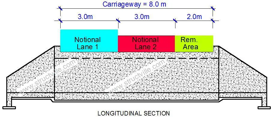
Width of carriageway = 8 m
Number of notional lanes = 8/3 = 2 notional lanes
Width of the remaining area = 8 – (2 × 3) = 2 m
(1) Case 1: Box culvert with no earth fill
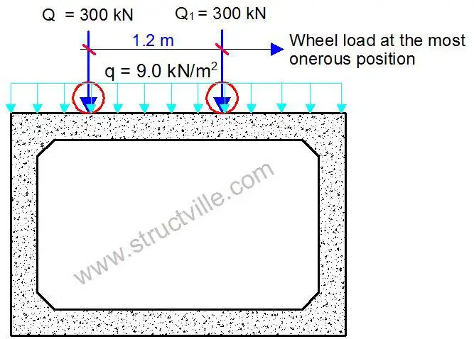
(a) Applying the recommended traffic actions on the notional lanes
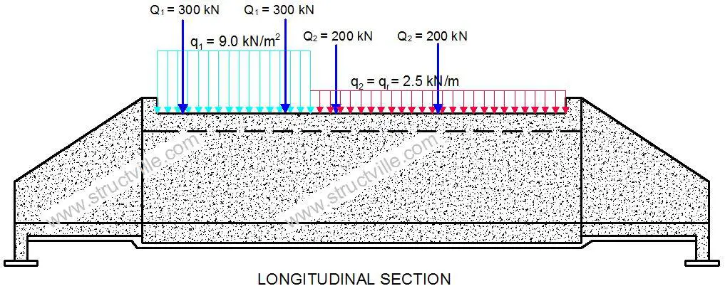
(b) Permanent actions
The self-weight of the structure should be calculated by Staad Pro software, but let us show how we can easily compute and apply it to the structure;
(i) Self-weight of top slab
Thickness of top slab = 300 mm = 0.3 m
Self weight of the slab per unit length = 0.3 m × 25 kN/m3 = 7.5 kN/m2
(ii) Permanent action from the asphalt layer
Thickness of asphalt = 75 mm = 0.075 m
Self weight of the asphalt per unit length = 0.075 m × 22.5 kN/m3 = 1.69 kN/m2
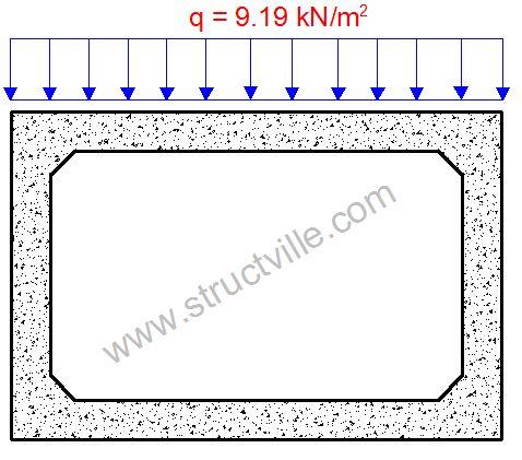
For the purpose of simplicity, let us combine these two actions such that the permanent action is given by gk = 7.5 + 1.69 = 9.19 kN/m2
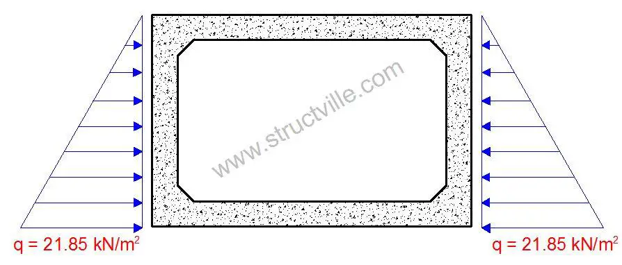
(iii) Earth Pressure
At rest earth pressure coefficient ko = 1 – sin (∅) = 1 – sin (30) = 0.5
Maximum earth pressure on the side walls p = koρH = 0.5 × 19 kN/m3 × 2.3m = 21.85 kN/m2
(iv) Live load Surcharge
Consider a live load surcharge of q = 10 kN/m2
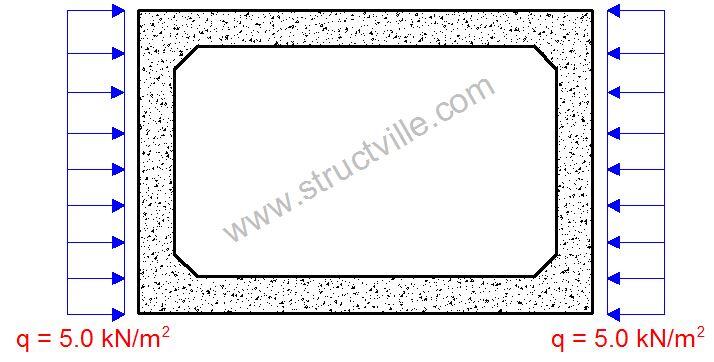
Therefore horizontal surcharge pressure = koq = 0.5 × 10 kN/m2 = 5.0 kN/m2
When the culvert is full, the hydrostatic pressure profile inside the culvert can also be easily obtained. However, this was not considered in this analysis.
(2) Case 2: Box culvert with 1.2 m thick earth fill
(a) Traffic Load on the Box Culvert
In this case, since the thickness of the fill is greater than 0.6 m, we are going to consider the wheel load of the traffic actions dispersed to the top slab of the culvert as a uniformly distributed load. The UDL of traffic action will not be considered.
For this case, let us use Load Model 1 of EN 1991-2 which is recommended by clause 4.9.1 of EN 1991-2. The tandem load can be considered to be dispersed through the earth fill and uniformly distributed on the top of the box culvert. The contact surface of the tyres of LM1 is 0.4m x 0.4m, which gives a contact pressure of about 0.9375 N/mm2 per wheel.
We are going to disperse the load through the earth fill to the box culvert by using the popular 2(vertical):1(horizontal) load increment method. This is the method recommended by BD 31/01, otherwise, Boussinesq’s method can also be used. However, clause 4.9.1 (Note 1) of EN 1991-2:2003 recommends a dispersal angle of 30° to the vertical for a well-compacted earth fill. A little consideration will show that this is not so far away from the 2:1 load increment method.
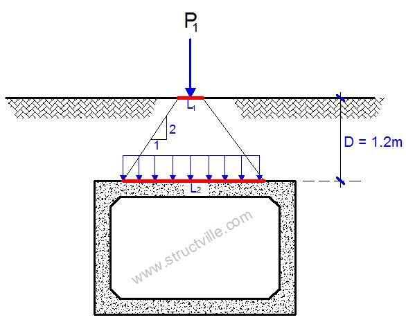
For the arrangement in Fig 9 above;
P1 = 150 kN
L1 = 0.4 m
L2 = 0.4 + D = 0.4 + 1.2 = 1.6 m
Therefore, the equivalent uniformly distributed load from each wheel to the culvert is;
qec = 150/(1.6 × 1.6) = 58.593 kN/m2
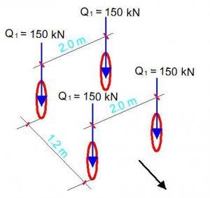
It is acknowledged that the pressure from each wheel in the axles can overlap when considering the tandem system as shown in the figure below. This is considered in the lateral and longitudinal directions.
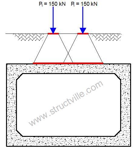
When considering the tandem system as shown in Figure 10;
∑Pi = 150 + 150 + 150 + 150 = 600 kN
L2 = 1.2 + 0.4m + 1.2m = 2.8 m (Spacing of wheels + contact length + depth of fill)
B2 = 2.0 m + 0.4m + 1.2m = 3.6 m (Spacing of wheels + contact length + depth of fill)
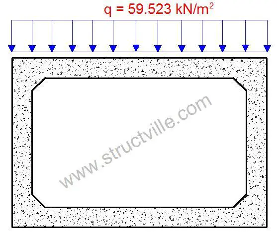
qec = 600/(2.8 × 3.6) = 59.523 kN/m2
As can be seen, the difference between considering the entire tandem system and one wheel alone is not much. But to proceed in this design, we will adopt the pressure from the tandem system.
Therefore the traffic variable load on the box culvert is given in Fig. 11 below;
[Get this publication on Design of Residential Buildings Using Staad, Orion, and Manual Calculations into your mailbox by clicking HERE or by clicking on the book cover]
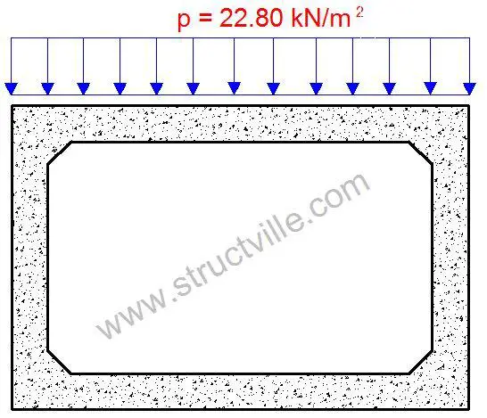
(b) Earth load on top of the box culvert
At a depth of 1.2 m, the earth pressure on the box culvert is given by;
p = 1.2 × 19 kN/m3 = 22.8 kN/m2
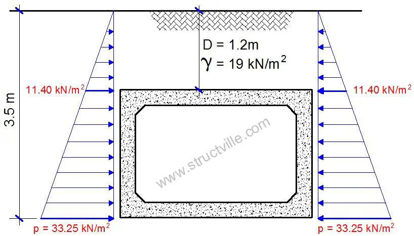
(c) Horizontal Earth Pressure on the Box Culvert
Since the box culvert is buried under the ground, the pressure distribution is as given in Figure 13.
The maximum pressure at the base of the culvert (at 2.3 m) is given by;
pmax = koρH = 0.5 × 19 kN/m3 × 3.5 m = 33.25 kN/m2
The minimum pressure at the top of the culvert (at 1.2 m below the ground) is given by;
pmin = koρH = 0.5 × 19 kN/m3 × 1.2 m = 11.40 kN/m2
(d) Surcharge load
The horizontal surcharge load distribution on the buried box culvert will be the same as that of case A.
Thank you for visiting Structville today. We are going to present the actual analysis and design of box culverts using Staad Pro in our next post which will come shortly. Please stay tuned and God bless you.





Good one.You are always on point,please keep up the good work.
good explanation
Thank you so much…
Thank you
Thanks a lot
Nice one sir. Really helpful
How do you apply loads on a multicell box culvert?
Do the horizontal load (braking / traction) get transferred to the box culvert? specially in case of railway loading. consider a cushion fill of 4m.. will it get transfered? Can i get any codal reference saying whether to consider it or not.
Do the horizontal load (braking / traction) get transferred to the box culvert? specially in case of railway loading. consider a cushion fill of 4m.. will it get transfered? Can i get any codal reference saying whether to consider it or not.
Nice one sir
thank you so much.
Wonderfull Engineer
Provide more insite in the structural world
thank you! clearly and insightful
I’ve always wondered what culverts were called as I see them everywhere. It’s interesting how culvert is a drainage system to convey stormwater across a roadway. Thanks for pointing out that any structure more than 6 m can be treated as a bridge instead. I definitely see the importance of culverts in construction and I would imagine that a contractor will want to use new and used culverts for many different reasons, including its durability.
This website is a blessing to young civil / structural engineers the world over. I especially love the first principles approach to analysis and design. God bless you.
Good lesson
Please can we have the hydraulics design calculations
Eng, how do you consider base pressures as the foundation base is subjected to some loading from the walls as well as reaction from the soil below ?
Please can you assist with the design calculations of cast in situ culvert foundations & bases for culverts.
Thanks for sharing.
Thank you for sharing this insightful article
Thank you very much
please can it be in PDF format as you always do engr including the culvert design with staadpro