Retaining walls are structures constructed for the purpose of retaining earth fill. There are different types of retaining walls such as cantilever retaining walls, gravity retaining walls, counterfort retaining walls, buttress walls, etc. Each of these has found wide applications in various civil engineering construction works such as embankments, highways, basements, etc.
Traditionally, cantilever retaining walls are designed as line elements where the width of the cantilever is analysed per unit strip (usually per metre length). The base of the cantilever is usually considered rigid, and as a result, a linear pressure distribution under the base is usually assumed.
However, when the dimensions of the retaining wall are such that a rigid behaviour cannot be obtained, or the soil is so soft or subjected to movement, then there will be significant soil-structure interaction. In this approach, the deformation of the soil and the structure itself contributes to the response of the structure to the externally applied load.
In this article, we are going to investigate the interaction of cantilever retaining walls with the soil supporting them in order to see how this affects the settlement, internal forces, and base pressure distribution. This will be carried out using Staad Pro software.
The factors usually checked out for in design of cantilever retaining walls are;
- (1) Overturning
- (2) Sliding
- (3) Bearing capacity
- (4) Uplift (rarely critical)
- (5) Structural resistance
Methodology
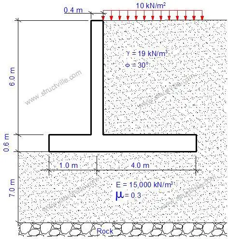
We are going to consider the analysis and design of the retaining wall with the dimensions and soil properties shown in Figure 1.
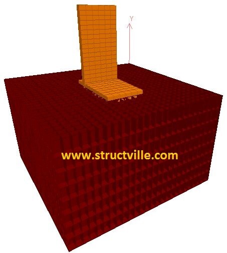
The retaining wall was modelled using concrete plate elements of mesh size 0.5m x 0.5m on Staad Pro software. The unit weight of concrete was set to be 24 kN/m3 for the computation of self-weight.
The soil elements were modelled using 8-noded solid element with the elastic properties indicated in Figure 1. Each soil element was modelled as a cuboid with a length and width of 0.5m, and thickness (depth) of 1m. The solid elements were stacked on each other to achieve the formation thickness of 7m. The rock layer was achieved by supporting the last nodes of the soil elements using pinned support. A width of 3m was adopted for modelling the retaining wall.
At ultimate limit state, the permanent actions (self-weight of concrete and earth fill) were factored with a partial factor of 1.35, while the variable action (surcharge) was multiplied by a partial factor of 1.5. The effect of groundwater was not considered in the analysis. The 3D rendering of the soil and retaining wall is shown in Figure 2. The concrete cantilever wall is shown in gold colour, while the soil element is shown in wine red colour (burgundy).
Results
(1) Settlement
The settlement profile and deflection of the retaining wall at the serviceability limit state are shown in Figure 3.
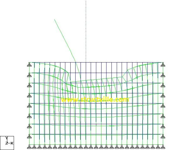
The maximum elastic settlement at the toe (SLS) = 19.647 mm
Elastic settlement at the heel (SLS) = 14.856 mm
Deflection at the free end of the cantilever = 35.493 mm
(2) Pressure distribution
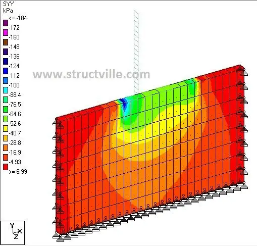
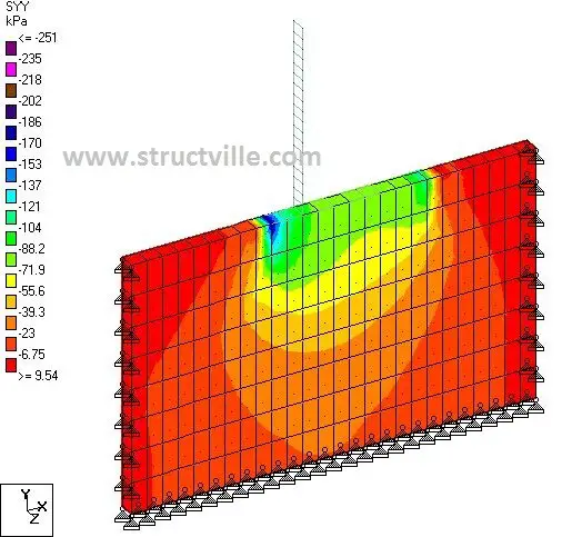
The pressure distribution under the retaining wall at the serviceability and ultimate limit states are shown in Figures 4 and 5 respectively. As expected, the maximum pressure occurred at the toe, while minimum pressure occurred at the heel. The pressure distribution was observed to be non-linear, but a little consideration will show that linear approximation can be adopted for design purposes. At SLS, a minimum pressure of 52.6 kPa was observed at the heel, and a maximum pressure of 184 kPa was found to be concentrated at the corners of the toe.
(3) Bending moment
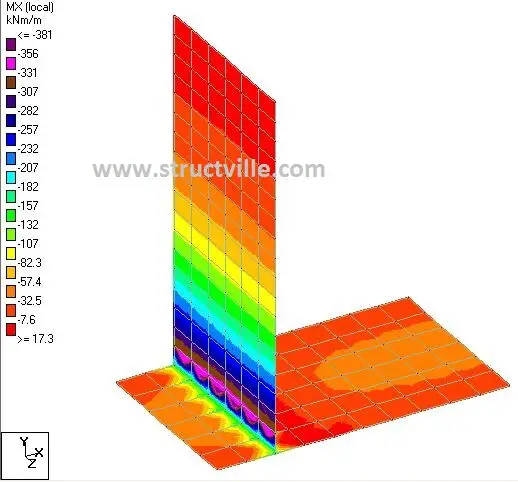
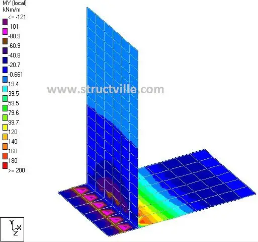
The bending moments on the wall at ULS are shown in Figures 6 and 7.
(4) Stability Analysis (SLS)
(a) Sliding
Summation of horizontal forces = 401.99 kN
Summation of vertical forces = 1876.8 kN
Let the coefficient of friction of the base against sliding be tan(2/3 x 30o) = 0.363
Factor of safety against sliding = [1876.8 x 0.363] / 401.99 = 1.69 (Okay)
(b) Overturning
Overturning moment = 2612.6 kNm
Stabilising moment = 12356.42 kNm
Factor of safety against overturning = 12356.42/2612.6 = 4.729 (Okay)
The design for the reinforcements can be done accordingly. Kindly carry out the manual analysis of the same retaining wall and forward it to ubani@structville.com for consideration.


