Every code of practice for bridge design has provision for modelling of traffic action as moving loads. This is similar to the idea of influence lines, where the wheel load action effect at the critical location of the influence line/surface is used in design combination. In this post, we are going to show how you can model bridges, and apply moving load on Staad Pro according to the principles of Eurocodes.
In the past, we have made publications on how you can apply Load Model 1 of EN 1991-2 on highway bridges. You can also read on how you can carry out grillage analysis of bridges using Staad Pro. Other publications such analysis of bridge deck girders under Load Model 1 using Staad Pro can also be considered to enhance your knowledge on the topic.
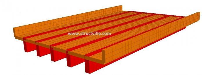
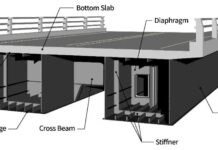
Let us consider a bridge deck with the configuration shown in Figure 1;
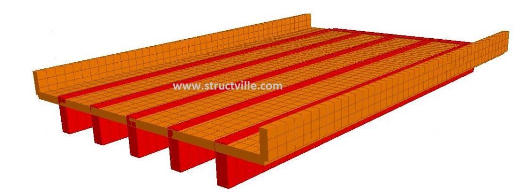
We can apply the tandem load of EN 1991-2 on the bridge deck in order to obtain the critical bending moment and shear forces. We have prepared a 21 page manual on how you can model a complete simply supported one-span bridge on Staad Pro. This can help you model a bridge of this nature by yourself on Staad Pro with full support of our technical team peradventure you need further help in getting it done. To obtain the publication for a nominal fee click HERE.
How to Apply Moving Load on Staad Pro
Step 1: Define the load
Go to → Loads → Definitions → Moving
Using the procedure described in Chapter 1, define the tandem wheel load of Eurocode on the bridge deck;
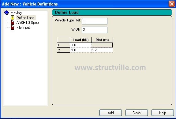
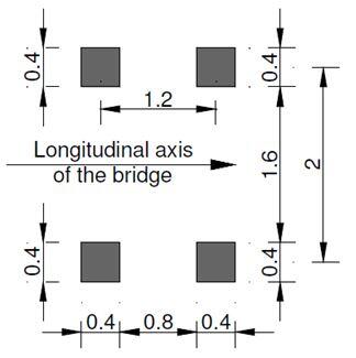
Please note that the vehicle definition shown in Figure 2 is based on Eurocode Load Model 1 for tandem load on notional lane 1. The configuration of the wheel load is shown in Figure 3. You can define as many vehicle wheel load configurations as applicable.
Step 2: Generate the moving load on the bridge
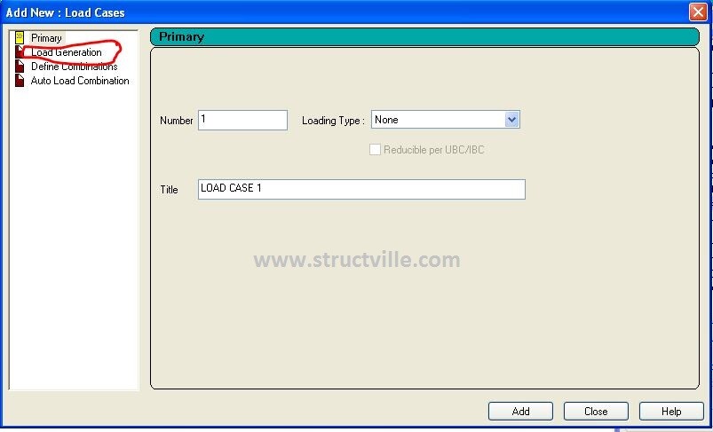
Go to → Load Case Details → Load Generation
When you click on Load Case details, click on Load Generation as circled in red pen in Figure 4, then click Add.
Go over to the right hand side of the screen (Load and Definitions) and click on the load generated, and click Add in order to define the exact details such as the starting point, location, and step increment. This is shown in Figure 5.
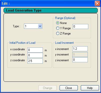
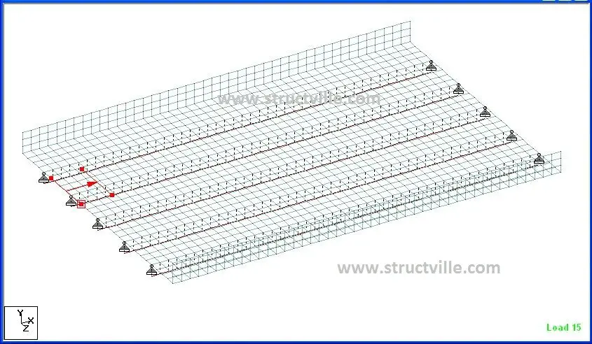
For this example, one of the loads generated is shown in Figure 6.
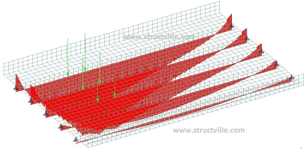
Having gotten here, you can analyse the structure and see the variation of bending moment and shear forces as the vehicle travels through the bridge.





Nice info.
I have few questions:
1. Under Load Generation Type, what is your recommended load increment to get the max moment and shear forces?
2. The info you have shared is for one vehicle load only. How will you load for other vehicle loads in other lanes?
3. Further to item 2, if there is 4 lanes for example, will you check moving loads two vehicles same direction on two lanes (1st and 2nd lane) and another two vehicle loads moving same direction but opposite (3rd and 4th lane) to mimic the actual traffic? Any tips or advise?
4. Lastly, As per AASHTO code, it was mentioned the vehicle load (tandem or truck) to be combined with lane load. How will you model or analyze this on staad? Is it correct that when a vehicle moves all other areas in the bridge will have a lane load?