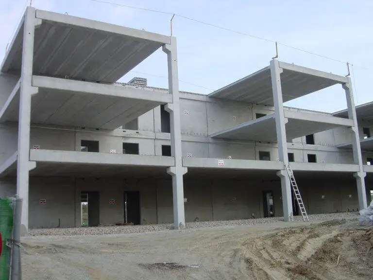
A corbel is a very short structural cantilever member projecting from a wall or a column for the purpose of carrying loads. In reinforced concrete structures, corbels are cast monolithically with the walls or columns supporting them. They are found mainly in bridges, industrial buildings, and commercial buildings with precast construction.
If a structure is subjected to in-plane forces, then the stress distribution will consist of normal stresses in the two planes (σx and σy) and an accompanying shear stress τxy. These stresses will lead to two principal stresses σ1 and σ2. If for instance σ1 is tensile and σ2 is compressive, then the external load on the structure can be idealized as being resisted by a combination of tensile and compressive stresses.
In reinforced concrete structures, the compressive stresses can be resisted by the concrete, while the tensile stresses can be resisted by the steel reinforcement. Generally, these are idealized by a series of concrete struts and steel ties, and forms the underlying principle behind the strut-and-tie method of design. Structures that can be designed using this method are pile caps, deep beams, corbels, half-joints, etc.
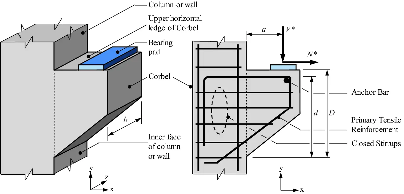
Under certain conditions, Eurocode 2 permits the use of strut and tie method for the analysis and design of corbels. According to clause 6.5.1 of EN 1992-1-1:2004, strut-and-tie method can be used where non-linear stress distribution exists (for example at supports, near concentrated loads or plain stress).
Strut-and-tie models utilize the lower-bound theorem of plasticity which can be summarized as follows: for a structure under a given system of external loads, if a stress distribution throughout the structure can be found such that;
(1) all conditions of equilibrium are satisfied and
(2) the yield condition is not violated anywhere,
Then the structure is safe under the given system of external loads.
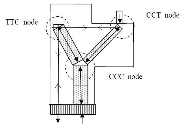
When using the strut−and-tie method of design, because the given structure is replaced by a pin-jointed truss, different types of nodes occur where members meet. These nodal zones need to be carefully designed and detailed.
(a) CCC Node: If three compressive forces meet at a node, it is called a CCC node. According to Eurocode 2 equation (6.60), the compression stress in each strut is restricted to a maximum value of 1.0(1 – fck/250)fcd.
(b) CCT node: If two compressive forces and a tie force anchored in the node through bond meet, it is called a CCT node. According to Eurocode 2 equation (6.61), the compression stress in each strut is restricted to a maximum value of 0.85(1 – fck/250) fcd.
(c) CTT node: If two tensile forces at a compressive force meet at a node it is called a CTT node. According to Eurocode 2 equation (6.62),
the compression stress in each strut is restricted to a maximum value of 0.75(1 – fck/250)fcd.
The following conditions are to be applied in the design of corbels;
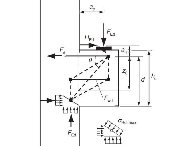
(1) Corbels with 0.4hc < ac < hc may be designed using a simple strut and tie model.
(2) For deeper corbels (ac < 0.4hc), other adequate strut and tie models may be considered.
(3) Corbels for which ac > hc may be designed as cantilever beams
(4) Unless special provision is made to limit horizontal forces on the support, or other justification is given, the corbel should be designed for the vertical force Fv, and a horizontal force Hc > 0.2Fv acting at the bearing area.
(5) The overall depth (hc) of the corbel should be determined from considerations of shear.
(6) The local effects due to the assumed strut and tie system should be considered in the overall design of the supporting member.
(7) The detailing requirements shall be met.
Design Example of a thick short corbel (ac < hc/2)
Design the corbel shown below. The bearing area of the support is 200 x 300 mm. The width of the corbel is 150 mm.
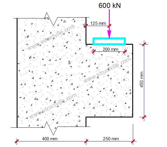
Materials
Concerete C30/35, fck = 30 N/mm2; fyk = 500 N/mm2
Design strength of concrete fcd = αccfck/γc = (0.85 x 30)/1.5 = 17 N/mm2
Design strength of steel fyd = fyk/γs = 500/1.15 = 435 N/mm2
Compressive strength of nodes;
CCC nodes:
σ1Rd,max = 1.0 x (1 – fck/250)fcd = 1.0 x (1 – 30/250) x 17 = 14.96 N/mm2
CCT nodes:
σ2Rd,max = 0.85 x (1 – fck/250)fcd = 0.85 x (1 – 30/250) x 17 = 12.716 N/mm2
CTT nodes:
σ3Rd,max = 0.75 x (1 – fck/250)fcd = 0.75 x (1 – 30/250) x 17 = 11.22 N/mm2
Actions
FEd = 600 kN
Load eccentricity with respect to the column side: e = 125 mm
The beam vertical strut width is evaluated by setting the compressive stress equal to σ1Rd,max:
x1 = FEd/σ1Rd,maxb = (600 x 103)/(14.96 x 350) = 114.6 mm
Node 1 is therefore located at x1/2 = 114.6/2 = 57.3 mm
Let the cover from the top of the cantilever to the reinforcements be 30 mm. Assuming 16 mm bars;
The effective depth d = 450 – 35 – (16/2) = 407 mm
The distance y1 of the node 1 from the lower border is evaluated setting the internal drive arm z equal to 0.8⋅d (z = 0.8 x 407 = 325.6 mm):
y1 = 0.2d = 0.2 x 407 = 81.5 mm
Rotational equilibrium: FEda = Fcz
a = ac + x1/2 = 125 + 57.3 = 182.3 mm
600 x 103 x 182.3 = Fc x 325.6
Fc = Ft = 335933.66 N = 335.93 kN
Node 1 verification;
σ = Fc / (b∙2y1) = (335.93 x 10³)/(350 x 2 x 81.5) = 5.89 N/mm2 < σ1Rd,max (14.96 N/mm2)
Main Top Reinforcement Design
As1 = Ft/fyd = (335.93 x 10³)/435 = 772 mm2
Provide 5H16 (As,prov = 1005 mm2)
Shear reinforcement design
The beam proposed in EC2 is indeterminate, then it is not possible to evaluate the stresses for each single bar by equilibrium equations only, but we need to know the stiffness of the two elementary beams shown below in order to make the partition of the diagonal stress [Fdiag = Fc/cosθ = FEd/sinθ] between them.
Based on the trend of main compressive stresses resulting from linear elastic analysis at finite elements, some researchers from Stuttgart have determined the two rates in which Fdiag is divided, and they have provided the following expression of stress in the secondary reinforcement.
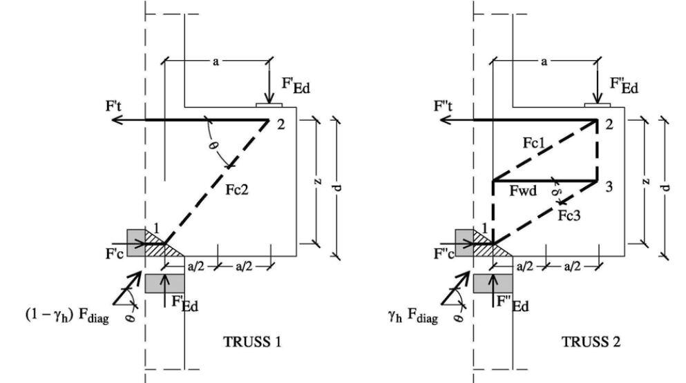
Fwd = [(2z/a – 1)/(3 + FEd/Fc)] x Fc = [(2(325.6/182.3) – 1)/(3 + 600/335.93)] x 335.93 = 180.525 kN
Asw = Fwd/fyd = (180.525 x 10³)/435 = 415 mm2 > k1As,prov = 0.25 x 1005 = 251.25 mm2
Trying 2 legs of H10 mm, Provide 4 number of H10 mm stirrups (Asw,prov = 628 mm2)
Node 2 verification, below the load plate
The node 2 is a tied-compressed node, where the main reinforcement is anchored; the compressive stress below the load plate is;
σ = FEd /(200 x 300) = (600 x 103)/(200 x 300) = 10 N/mm2 < σ2Rd,max (12.716 N/mm2) Okay
Detailing Requirements
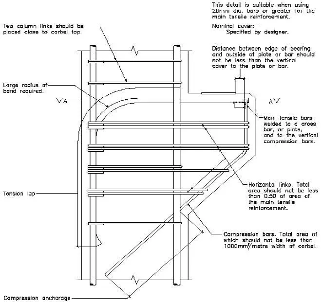
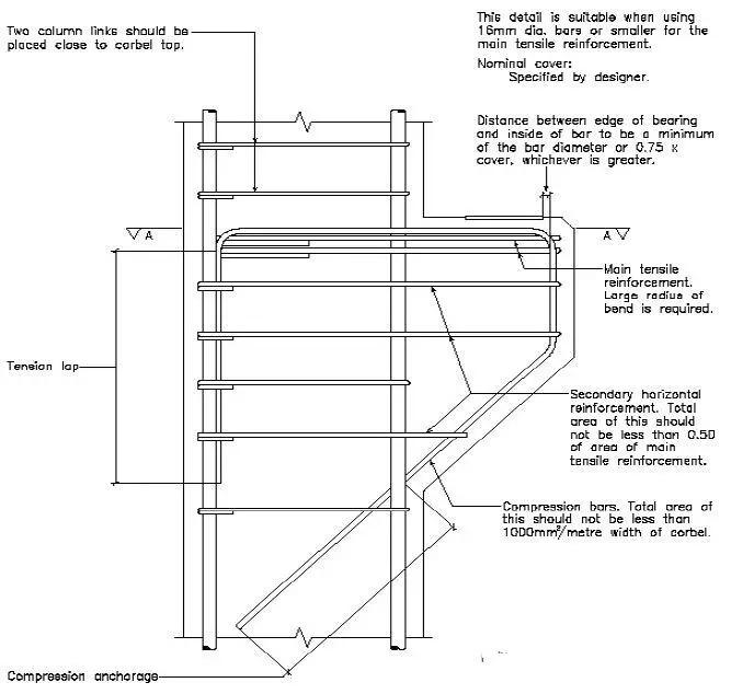
(1) The reinforcement, corresponding to the ties considered in the design, should be fully anchored beyond the node under the bearing plate by using U-hoops or anchorage devices, unless a length lb,net is available between the node and the front of the corbel, lb,net should be measured from the point where the compression stresses change their direction.
(2) In corbels with hc > 300 mm, when the area of the primary horizontal tie As is such that (where Ac denotes the sectional area of the concrete in the corbel at the column), then closed stirrups, having a total area not less than |0.4|As, should be distributed over the effective depth d in order to cater for splitting stresses in the concrete strut. They can be placed either horizontally or inclined.
