P-delta is a geometric non-linear effect that occurs in structures that are subjected to compressive loads and lateral displacement. Under the action of compressive loads and lateral displacement, tall slender structures will experience additional stresses and deformations due to the change of position of the structure. First-order structural analysis will normally consider small displacements and will compute the equilibrium of the structure and internal stresses based on the undeformed geometry. However, second-order analysis considers the deformed geometry of the structure and may require an iterative approach for the computation of equilibrium.
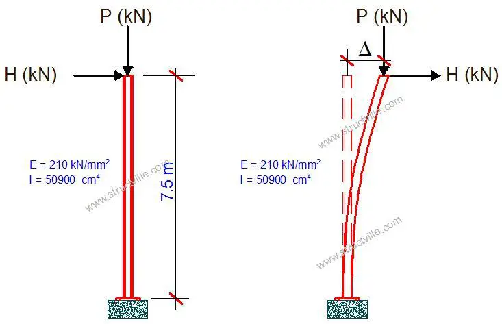
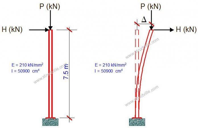
During the simultaneous action of vertical and horizontal loads, the structure deflects due to the action of the horizontal load. As the structure deflects, the position of the vertical load P shifts by a distance ∆ such that the vertical load instead of acting axially along the column now induces a moment reaction at the base P∙∆. The interaction of the compressive force (P) and lateral displacement (∆) to produce additional secondary effects in a structure is handled under P-delta analysis.
Solved Example
Let us quickly investigate the effect of P-delta on the cantilever column loaded as shown below.

Let;
P = 150 kN
H = 20 kN
1st iteration
First-order moment at the base of the cantilever M = H x L = 20 kN x 7.5m = 150 kNm
So, the lateral displacement (Δ1) at the column tip = ML2/3EI = (150 x 7.52)/(3 x 210 x 106 x 4.09 x 10-4) = 0.0327 m
Also, the vertical load P acting on displaced Δ1 column tip generates additional moment M1 at the base.
M1 = P x Δ1 = 150 x 0.0327 = 4.905 KNm
The total moment at the base MT1 = M + M1 = 150 + 4.905 = 154.905 kNm
The modified horizontal displacement “Δ2” undergone for the first modified moment MT1
Δ2 = (MT1L2)/ (3EI) =(154.905 x 7.52)/(3 x 210 x 106 x 4.09 x 10-4) = 0.0338 m
2nd iteration
The vertical load P acting on the newly displaced column tip (Δ2 – Δ1) results in additional moment M2 at the base;
M2 = P x (Δ2 – Δ1) = 150 x (0.0338 – 0.0327) = 0.165 KNm
Now, the total moment at the base, MT2 = (M + M1 + M2) = (MT1 + M2) = 154.905 + 0.165 = 155.07 KNm
The second modified horizontal displacement Δ3 against the second modified Moment Mt2
Δ3 = (MT2L2)/3EI = (155.07 x 7.52)/(3 x 210 x 106 x 4.09 x 10-4) = 0.0338 m
For all practical purposes, the analysis above will be taken to have converged.
There are two types of P-Delta effects which are;
- P-“large” delta (P-∆) – a structure effect
- P-“small” delta (P-δ) – a member effect
While large delta is associated with the global displacements and effects on the structure, small delta takes into account the local effects and displacements of the members. The sensitivity of a structure to P-Delta effect is related to the magnitude of the axial load P, stiffness/slenderness of the structure as a whole, and slenderness of individual elements. Second-order effects are prominent in structures under high compressive load with low stiffness or high slenderness. The closer the compressive load is to the critical buckling load, the more sensitive the structure is to P-delta effects.
P-delta analysis combines two approaches to reach a solution which are;
- Large-displacement theory, and
- Stress stiffening
In large-displacement theory, the resulting forces and moments take full account of the effects due to the deformed shape of both the structure and its members. The large-displacement theory identifies the fact that there is a clear distinction between the deformed and undeformed shapes of the structure. In small displacement theory, the strains and the displacements are small, while large-displacement theory assumes small strains in the structure but large displacements.
Stress stiffening is concerned with the effect of stress state on a structure’s stiffness. For instance, tensile loads straighten the geometry of an element thereby stiffening it. On the other hand, compressive loads accentuate deformation thereby reducing the stiffness of the element. The effect of stress stiffening is accounted for by generating and then using an additional stiffness matrix (stress stiffness matrix) for the structure. The stress stiffness matrix is added to the regular stiffness matrix in order to give the total stiffness.
Second-order effects have been incorporated in many codes of practice for the design of concrete, timber, and steel structures. This has usually been included in the design equations and verifications to ensure that the behaviour of the structure stays within the prescribed limits. However, with the availability of advanced computational power of software, engineers are now encouraged to carry out full second-order analysis for design purposes.
P-Delta Analysis on Staad Pro
The procedure adopted by Staad Pro for P-delta analysis are as follows;
- First, the primary deflections are calculated based on the provided external loading.
- Primary deflections are then combined with the originally applied loading to create the secondary loadings. The load vector is then revised to include the secondary effects.
- A new stiffness analysis is carried out based on the revised load vector to generate new deflections.
- Element/Member forces and support reactions are calculated based on the new deflections.
For proper analysis of P-delta effect in Staad, it is important that the vertical and horizontal load cases be combined under one single load case. This can be achieved using the ‘REPEAT LOAD CASE’, which allows the user to combine previously defined primary load cases to create a new primary load case. A REPEAT LOAD is treated as a new primary load which enables the P-Delta analysis to reflect the correct secondary effects. It is important to note that ‘LOAD COMBINATIONS’ command will algebraically combine the results such as displacements, member forces, reactions, and stresses of previously defined primary loadings evaluated independently. Therefore, it is not suitable for P-Delta analysis.
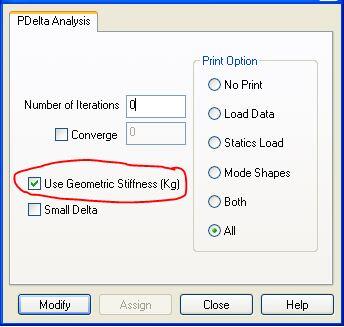
Furthermore, one can perform the P-Delta Analysis in Staad directly by considering the Geometric Stiffness Matrix [KG]. In this approach, the stress stiffening effect due to the axial stress is used directly to modify the actual Stiffness Matrix [K]. In the view of this approach, the compressive force (depending on its magnitude) reduces the lateral load-carrying capacity of the structure. This ultimately modifies the geometric stiffness of the member and is referred to as ‘stress softening effect’. In Staad, the change in the GEOMETRIC STIFFNESS from [K] to [K + KG] can be achieved by using the KG option as shown below.

So, by this approach the P-Delta stiffness equation is directly linearized by the [K + KG] matrix and the solution can be obtained directly and exactly, without iteration.
According to Staad Pro technical manual, there are two options in carrying out P-Delta analysis on Staad;
(1) When the CONVERGE command is not specified: The member end forces are evaluated by iterating “n” times. The default value of “n” is 1 (one).
(2) When the CONVERGE command is included: The member end forces are evaluated by performing a convergence check on the joint displacements. In each step, the displacements are compared with those of the previous iteration in order to check whether convergence is attained. In case “m” is specified, the analysis will stop after that iteration even if convergence has not been achieved. If convergence is achieved in less than “m” iterations, the analysis is terminated. (DO NOT ENTER “n” when CONVERGE is provided).
(3) To set convergence displacement tolerance, enter SET DISPLACEMENT f command. Default is maximum span of the structure divided by 120.
Solved Example
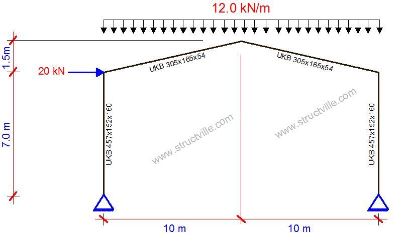
Let us consider the portal frame loaded as shown shown below.

| Action Effect | 1st order linear analysis | P-delta (1 iteration) | P-delta (2 iterations) | P-delta (5 iterations) | P-delta (10 iterations) | P-delta (15 iterations) |
| Displacement (mm) | 126.204 | 143.634 | 146.602 | 147.235 | 147.239 | 147.239 |
| Maximum bending Moment (kNm) | 406.704 | 425.321 | 427.837 | 428.322 | 428.325 | 428.325 |
| VB (kN) | 128.343 | 128.343 | 128.343 | 128.343 | 128.343 | 128.343 |
| HB (kN) | 58.101 | 58.101 | 58.101 | 58.101 | 58.101 | 58.101 |
As can be seen from the table above, 5 to 10 iterations is sufficient for second-order analysis of portal frames for practical purposes. While internal forces and displacements varied with second-order analysis, the equilibrium of the structure was maintained.


It would be pretty interesting to have a printable version of these articles along with the published ones.
Thank you
Best regards
Reza Zarghami
pure love