Checking for deflection is an important serviceability limit state (SLS) requirement in the design of structures. This check ensures that the structure does not deflect excessively in a manner that will impair the appearance, cause cracking to partitions and finishes, or affect the functionality or stability of the structure. In Eurocode 2, the deflection of a structure may be assessed using the span-to-effective depth ratio approach, which is the widely used method. It is also allowed to carry out rigorous calculations in order to determine the deflection of a reinforced concrete structure, which is then compared with a limiting value.
According to clause 7.4.1(4) of EN 1992-1-1:2004, the appearance of a structure (beam, slab, or cantilever) may be impaired when the calculated sag exceeds span/250 under quasi-permanent loads. However, span/500 is considered an appropriate limit for good performance.
Using the span-to-effective depth approach, the deflection of a structure must satisfy the requirement below;
Allowable l/d = N × K × F1 × F2 × F3 ≥ Actual l/d
Where;
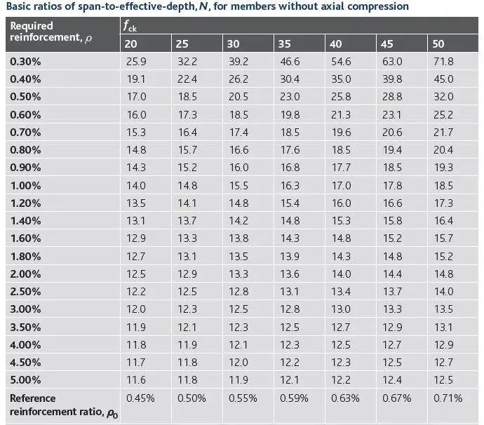
N is the basic span-to-effective depth ratio which depends on the reinforcement ratio, characteristic strength of the concrete, and the type of structural system. The expressions for calculating the limiting value of l/d are found in exp(7.16) of EN 1992-1-1:2004. The expressions are given as follows;
l/d = K[11 + 1.5√fck(ρ0/ρ) + 3.2√fck(ρ0/ρ – 1)1.5] if ρ ≤ ρ0
l/d = K[11 + 1.5√fck(ρ0/(ρ – ρ’)) + 0.0833√fck(ρ0/ρ)0.5] if ρ > ρ0
Where:
l/d is the limit span/depth ratio
K is the factor to take into account the different structural systems
ρ0 is the reference reinforcement ratio = √fck /1000
ρ is the required tension reinforcement ratio at midspan to resist the moment due to the design loads (at supports for cantilevers)
ρ’ is the required compression reinforcement ratio at midspan to resist the moment due to the design loads (at supports for cantilevers)
fck is the characteristic compressive strength of the concrete in N/mm2
The values of K for different structural systems are given in Table 1;
Table 1: Values of K for different structural systems
| Structural System | K |
| Simply supported beam, one or two way spanning simply supported slab | 1.0 |
| End span of continuous beam or one-way continuous slab or two-way spanning slab continuous over one long side | 1.3 |
| Interior span of beam or one way or two-way spanning slab | 1.5 |
| Slab supported on columns without beams (flat slab) | 1.2 |
| Cantilever | 0.4 |
Some design aids are available for the evaluation of the limiting span/effective ratio. This is shown in Table 2 below (culled from Goodchild, 2009) and has been derived for K = 1.0 and ρ’ = 0.
Table 2: Basic ratios of span-to-effective-depth for members without axial compression (Goodchild, 2009)

For the table above, ρ = As/bd (note that As is the area of steel required and not the area of steel provided). For T beams, ρ is the area of reinforcement divided by the area of concrete above the centroid of the tension reinforcement.
F1 = factor to account for flanged sections.
When beff/bw = 1.0, F1 = 1.0
When beff/bw is greater than 3.0, F1 = 0.8.
Intermediate values of beff/bw can be interpolated between 1.0 and 3.0
F2 = factor to account for brittle partition in long spans.
In flat slab where the longer span is greater than 8.5m, F2 = 8.5/leff
In beams and slabs with span in excess of 7.0m, F2 = 7.0/leff
F3 = factor to account for service stress in tensile reinforcement = 310/σs ≤ 1.5
Conservatively, if a service stress of 310 MPa is assumed for the designed reinforcement As,req, then F3 = As,prov/As,req ≤ 1.5
More accurately, the serviceability stress in the reinforcement may be stimated as follows;
σs = σsu[As,req/As,prov](1/δ)
Where;
σsu is the unmodified SLS steel stress taking account γM for reinforcement and of going from ultimate actions to serviceability actions.
σsu = fyk/γs(Gk + ψ2Qk)/(1.25Gk + 1.5Qk)
As,req/As,prov = Area of steel required divided by the area of steel provided
1/δ = factor to un-redistribute ULS moments
References
(1) EN 1992-1-1:2004 – Eurocode 2: Design of concrete structures – Part 1-1: General rules and rules for buildings. European Committee For Standardization
(2) Goodchild C.H. (2009): Worked Examples to Eurocode 2: Volume 1 (For the design of in-situ concrete elements in framed buildings to BS EN 1992-1-1:2004 and its UK National Annex 2005). MPA – The concrete Centre
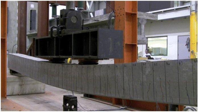
Cover image credit: Sharooz et al (2014): Flexural Members with High-Strength Reinforcement: Behavior and Code Implications. ASCE Journal of Bridge Engineering Volume 19 Issue 5


