Surcharge pressure on earth retaining walls can arise from different sources such as loads from adjacent buildings, fills, roadways and traffic actions, construction activities, and undulating/uneven ground surfaces, etc. Lateral pressures caused by surcharge loading may be calculated depending on the type of surcharge and the nature of load distribution. Elastic vertical stress calculated in the soil at the location is multiplied by the appropriate earth pressure coefficient to obtain the lateral pressure. In this article, we are going to evaluate the surcharge pressure exerted on a retaining wall from a nearby pad footing.
In geotechnical engineering, equations have been developed to compute stresses at any point in a soil mass based on the theory of elasticity. In non-elastic soil masses, the theory of elasticity still holds good as long as the stresses are relatively small, especially in overconsolidated soils. The real requirement in this case is the presence of constant ratio between the stresses and the strains, and not that soil is actually an elastic material. When a load is applied on a soil surface, it increases the vertical stress within the soil mass. The increased stress is greatest directly under the loaded area, but also extends indefinitely to other areas. Equations are available in geotechnical engineering textbooks for point loads, line loads, strips, and uniform pressure loads.
Standard textbooks provide solutions for vertical stress, σ’v,z, at depth z under a corner of a rectangular area carrying a uniform pressure q.
It is usually in the form;
σ’v,z = qK
where;
q = uniform pressure
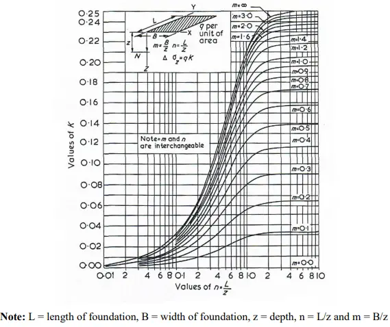
K = coefficient. Values of K are provided for different aspect ratios of the loaded area to depth. Fadum’s chart (shown below) can be used to obtain the influence coefficients.
The method of superposition can be used to determine the vertical stress under any point within or outside the loaded area. Generally, the effects of patch loads are derived by calculating pressures as if the load extends to the wall, and then subtracting the pressure for the patch load that does not exist. This is shown in the illustration below.
In the figure below, the surcharge from the pad footing is to be evaluated at different points on the retaining wall viz E,F, and G.

At point E;

Pressure at E = Pressure at the corner of rectangle EABH – Pressure at the corner of rectangle EDCH
At point F;

Pressure at F = Pressure at the corner of rectangle FJAE + Pressure at the corner of rectangle FJBH – Pressure at the corner of rectangle FIDE – Pressure at the corner of rectangle FICH
At point G;
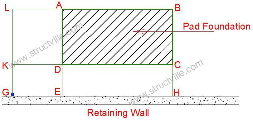
Pressure at G = Pressure at corner of rectangle GLBH – Pressure at corner of rectangle GLAE – Pressure at corner of rectangle GKCH + Pressure at corner of rectangle GKDE
Solved Example
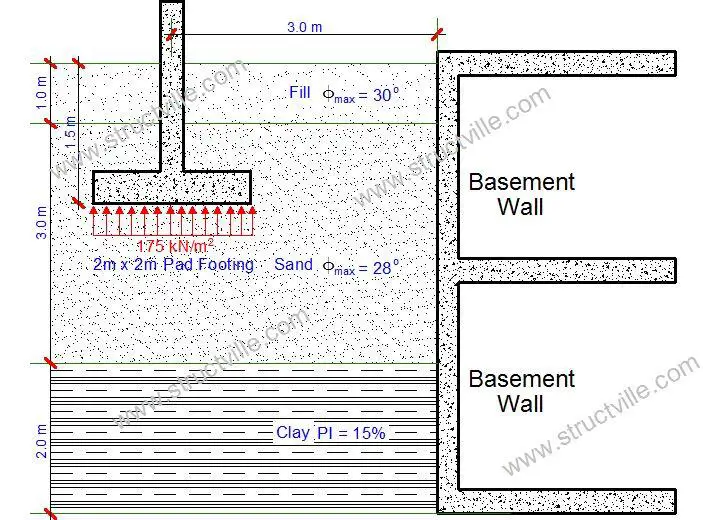
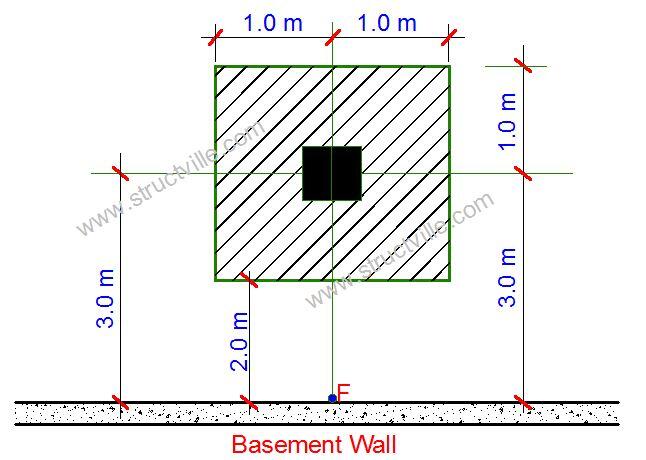
Calculate the lateral pressures caused by the existing pad foundation adjacent to the proposed basement shown below. The soffit of the pad is 2 m x 2 m in plan and bears at 175 kN/m2 at 1.5 m below the existing ground level. Assume the soil strata and soil properties as shown below.
Solution
Earth Pressure coefficients
At rest earth pressure coefficient for fill = Ko = 1 – sinφ = 1 – sin(30) = 0.5
At rest earth pressure coefficient for sand = Ko = 1 – sinφ = 1 – sin(28) = 0.53
At rest earth pressure coefficient for clay (using effective stress approach) φ’ for clay of plasticity index of 15% = 30° = Ko,d = (1 – sinφ) x OCR0.5
Assuming overconsolidation ratio (OCR) of 2.0; = 1 – sin(28) x 20.5 = 0.707
Pressure calculation
Pressures are calculated at a corner of a rectangular area viz:
Pressure at F = 2 x [(pressure at F for a rectangle 4 m x 1 m) – (pressure at F for a rectangle 2 m x 1 m)]
At 1.5m below ground level; take z below footing base = 0
(For 4 x 1m rectangle)
m = L/Z = 4/0 = ∞
n = B/Z = 1/0 = ∞
Hence from Fadum’s chart, K = 0.25
(For 2 x 1m rectangle)
m = L/Z = 2/0 = ∞
n = B/Z = 1/0 = ∞
Hence from Fadum’s chart, K = 0.25
Pressure at P = 2[(175 x 0.25) – (175 x 0.25)] = 0
At 3.0 m below ground level; take z below footing base = 1.5 m
(For 4 x 1m rectangle)
m = L/Z = 4/1.5 = 2.67
n = B/Z = 1/1.5 = 0.667
From Fadum’s chart, K = 0.162
(For 2 x 1m rectangle)
m = L/Z = 2/1.5 = 1.333
n = B/Z = 1/1.5 = 0.667
Hence from Fadum’s chart, K = 0.16
Pressure at P = 2 x [(175 x 0.162) – (175 x 0.16)] = 0.7 kN/m2
At 4.0 m below ground level; take z below footing base = 2.5 m
(For 4 x 1m rectangle)
m = L/Z = 4/2.5 = 1.6
n = B/Z = 1/2.5 = 0.4
From Fadum’s chart, K = 0.113
(For 2 x 1m rectangle)
m = L/Z = 2/2.5 = 0.8
n = B/Z = 1/2.5 = 0.4
Hence from Fadum’s chart, K = 0.095
Pressure at P = 2 x [(175 x 0.113) – (175 x 0.095)] = 6.3 kN/m2
At 5.0 m below ground level; take z below footing base = 3.5 m
(For 4 x 1m rectangle)
m = L/Z = 4/3.5 = 1.142
n = B/Z = 1/3.5 = 0.285
From Fadum’s chart, K = 0.08
(For 2 x 1m rectangle)
m = L/Z = 2/3.5 = 0.571
n = B/Z = 1/3.5 = 0.285
Hence from Fadum’s chart, K = 0.062
Pressure at P = 2 x [(175 x 0.08) – (175 x 0.062)] = 6.3 kN/m2
At 6.0 m below ground level; take z below footing base = 4.5 m
(For 4 x 1m rectangle)
m = L/Z = 4/4.5 = 0.889
n = B/Z = 1/4.5 = 0.222
From Fadum’s chart, K = 0.056
(For 2 x 1m rectangle)
m = L/Z = 2/4.5 = 0.444
n = B/Z = 1/4.5 = 0.222
Hence from Fadum’s chart, K = 0.040
Pressure at P = 2 x [(175 x 0.056) – (175 x 0.04)] = 5.6 kN/m2
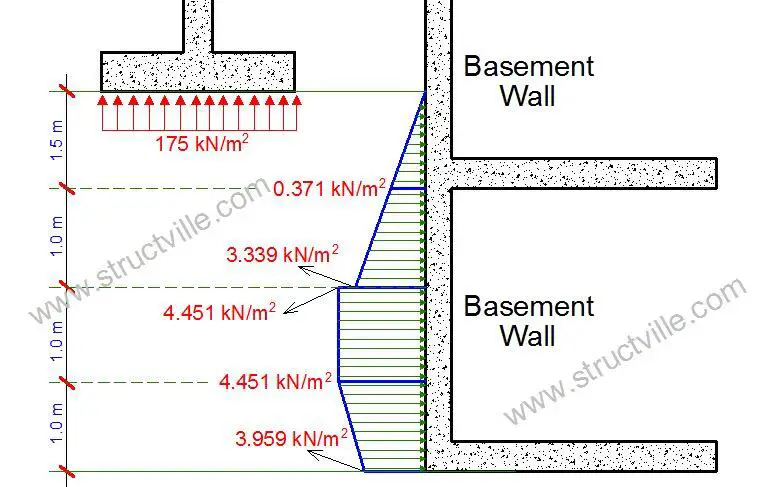
The at rest surcharge pressure on the retaining wall is therefore given by;
At 1.5m below the ground level; σ’kh = KoP = 0
At 3.0m below the ground level; σ’kh = KoP = 0.53 x 0.7 = 0.371 kN/m2
At 4.0m below the ground level; σ’kh = KoP = 0.53 x 6.3 = 3.339 kN/m2
At 4.0m below the ground level; σ’kh = KoP = 0.707 x 6.3 = 4.451 kN/m2
At 5.0m below the ground level; σ’kh = KoP = 0.707 x 6.3 = 4.451 kN/m2
At 6.0m below the ground level; σ’kh = KoP = 0.707 x 5.6 = 3.959 kN/m2
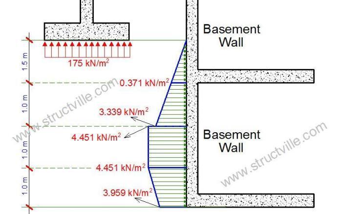
The characteristic surcharge pressure distribution on the basement wall from the pad footing is therefore given below;





Am so impressed with what you are doing, keep it up and may the Lord bless you.
Informative
Great job as always Engineer.