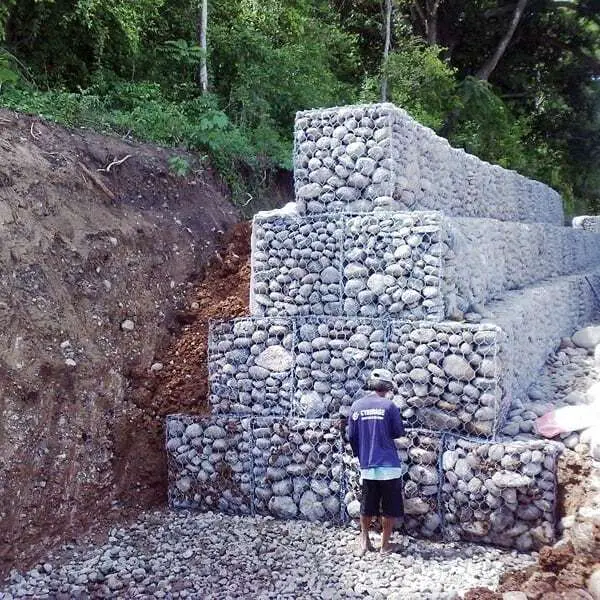
Gabion walls are made up of row upon row of orthogonal cages or baskets (gabions) which are filled with rock fragments/cobbles and tied together. This arrangement forms a block of gravity structure that is able to withstand lateral pressure on it. Furthermore, the permeability of the rock fragments and the flexibility of gabion cages make them particularly suitable for use at sites which are liable to become saturated and where the foundation is composed of relatively compressible materials.
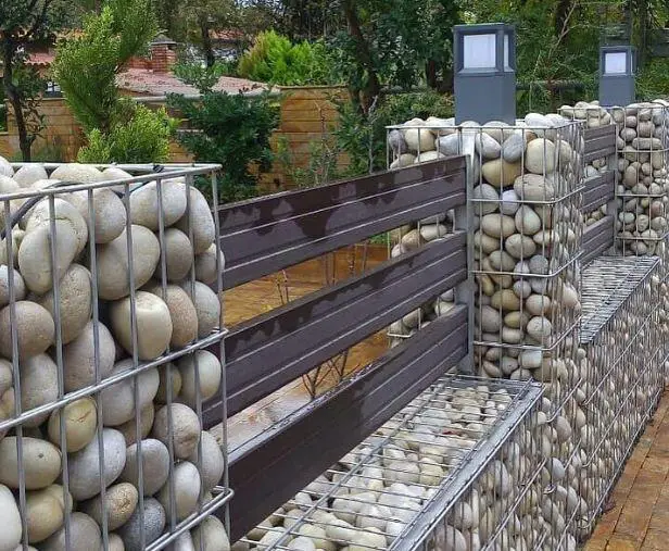
Gabion walls are relatively simple to construct. Where suitable rock is readily available, the use of gabion walls is particularly attractive for reasons of economy and speed of construction. In more recent times, gabion walls are generally used as decorative walls in compounds or gardens and are aesthetically pleasing. However, gabion walls can be designed as retaining structures.
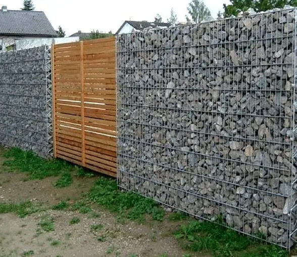
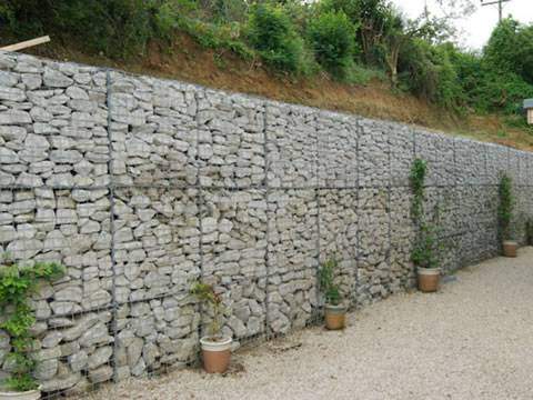
When gabions are to be used as retaining structures, they should be considered as gravity retaining walls. There is currently no universally accepted method for designing the individual gabion units. The individual units are placed on each other to form a stable gabion wall. The basic shape of a gabion wall is trapezoidal, but the front and rear faces may be straight or stepped.
It is recommended that back batter be provided for walls higher than about 3 m to improve stability and even out ground bearing pressures. A variety of cage sizes can be produced using suitable materials to suit the terrain. Gabion units are normally in modules of 2 m x 1 m x 1 m.
However, the design method for verification and appropriate functionality of a gabion wall can be carried out at the ultimate limit state analysis (ULS), verifying the following issues;
- Soil Bearing: The base pressure applied by the wall must not exceed the ultimate bearing capacity of the supporting soil.
- Sliding Resistance: There must be an adequate factor of safety for sliding between the base of the wall and the underlying soil due to the lateral earth pressure. Active earth pressure conditions should be assumed.
- Overturning stability: The overturning of the wall due to horizontal earth pressure forces when the retained soil mass become unstable (active failure) should satisfy the required conditions.
- Internal stability verification: For each layer of gabion a bearing capacity and sliding resistance verification should be made
- Global Stability
Design Considerations of Gabion Walls
The maximum pressure transferred from the gabion wall to the ground should be compared with the safe bearing capacity of the soil. This issue depends on the type of gabion foundation also, which for this case it is considered a non-stiff footing (the gabion is not placed on top of concrete).
Since gabion retaining walls consist of several layers, the internal stability verification should verify that these layers are not collapsing, neither sliding nor the bearing capacity of lower layers lesser than required. These conditions must be satisfied for each layer starting from the top layer to the bottom layer.
The overturning stability of the gabion retaining wall ensures that the soil retained behind the gabion wall is not causing lateral collapse of the wall. For this analysis, it is assumed the gabion wall is rigid body, with no sliding occurrence or partial breakdown between layers. The stabilising force is the weight of the gabion wall, while the destabilising force is the lateral pressure from the retained material or surcharge.
Limit state checks should be carried out at selected planes through the gabion wall, ignoring the resistance contributed by the cage material and the connections between the cages. For stepped walls, stability checks should be carried out at each major change in section shape.
In order to limit deformation, gabion walls should be proportioned in such a way that the resultant force acts within the middle third of the wall’s cross-section. The mobilised angle of wall friction, δ, used in the design should not exceed ϕ’/2, where ϕ’ is the angle of shearing resistance of the compacted backfill. In order for the assumption of δ = ϕ’/2 to hold, the gabion infill must be placed in such manner to achieve a dense mass which will not settle relative to the backfill after construction. Otherwise δ should be assumed to be zero. For a wall to be founded on relatively compressible materials, δ should also be assumed to be zero.
Materials for construction of gabion retaining walls
(1) Gabion Baskets
Gabion baskets can be made from a range of materials. Nylon, polypropylene and polyethylene grids have been used. They have the advantage of being lightweight and corrosion-resistant. However, these materials are susceptible to attack by fire and ultraviolet light. A material widely used in the commercial production of gabions is steel wire-mesh, of which there are two types, hexagonal woven and square welded.
The wires used for the wire-mesh in gabion baskets should be mild steel wire with a minimum tensile strength of 350 N/mm2. For permanent applications, the wires should be at least 2.7 mm in diameter and galvanized. Where it is suspected that the infill or retained materials or groundwater are aggressive, the wire mesh should be protected with PVC coating.
(2) Infill Material
Rock used for filling gabions should be sound, clean and well-graded. The maximum size of the rock should not exceed two-thirds the depth of the gabion to be filled or 300 mm, whichever is less. The preferred size is 150 mm to 300 mm. The smallest dimension of the rock should at least be twice the largest dimension of the mesh aperture.
(3) Backfill, Filter, and Drainage Materials
For a partially-submerged gabion wall, a free-draining granular backfill should be provided so that water pressure will not build up behind the wall when the water level in front of the wall is lowered.
Drainage Considerations for Gabion Walls
A geotextile filter should be provided behind the rear face of the gabion wall to prevent the migration of fines from the backfill into the coarse rock infill. Drainage layers at the rear face are normally not warranted. However, a drainage layer of adequate permeability should be provided at the base of the wall to guard against erosion of the foundation material.
The high permeability of the gabion units will permit direct infiltration through the body of the wall at times of heavy rainfall. In order to minimize the possibility of saturation and erosion of the foundation material under a non-submerged gabion wall, it is good practice to provide a blinding layer with adequate drainage provisions at the level of the foundation. For submerged gabion walls, appropriate measures should be incorporated to prevent scouring and erosion of the foundation.
Design Example of Gabion Walls
In the example below, a 3 m high gabion retaining wall is to be designed according to the requirements of Eurocode 7 (EN 1997-1).
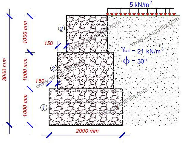
The design parameters and loadings are as follows;
Wall geometry
Width of gabion 1; w1 = 2000 mm
Height of gabion 1; h1 = 1000 mm
Width of gabion 2; w2 = 1700 mm
Height of gabion 2; h2 = 1000 mm
Step to front face between courses 1 and 2; s2 = 150 mm
Width of gabion 3; w3 = 1400 mm
Height of gabion 3; h3 = 1000 mm
Step to front face between courses 2 and 3; s3 = 150 mm
Wall inclination; ε = 0 deg
Gabion properties
Unit weight of fill; γd = 16.0 kN/m3
Friction between gabions; δbg.k = 35.0 deg
Loading
Permanent surcharge; ρo,G = 5 kN/m2
Soil properties
Slope of retained soil; β = 0.0 deg
Characteristic effective shearing resistance angle; ϕ’r.k = 30.0 deg
Characteristic saturated density of retained soil; γsr = 21.0 kN/m3
Coefficient for wall friction; kmembrane = 0.75
Wall friction angle; δr.k = 22.5 deg
Characteristic base friction angle; δbb.k = 30.0 deg
Soil bearing capacity; q = 100 kN/m2
The calculation sheet has been made available in PDF format and can be downloaded below;
Thank you for visiting Structville today. God bless you.

