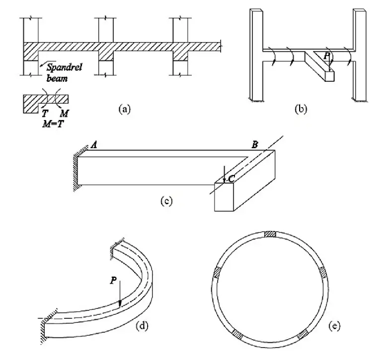
A full torsional design covering the ultimate and serviceability limit states is required when the equilibrium of a structure is dependent on the torsional resistance of the member. Reinforced concrete (RC) beams are subjected to torsion when the point of application of loads does not coincide with the shear centre of the beams. This can be due to the arrangement of the beams or the loading pattern as can be found in circular or canopy beams.
According to clause 6.3.1(3) of EN 1992-1:2004, the torsional resistance of a section may be calculated on the basis of a thin-walled closed section, in which equilibrium is satisfied by a closed shear flow. Solid sections may be modelled by equivalent thin-walled sections. Complex shapes, such as T-sections, may be divided into a series of sub-sections, each of which is modelled as an equivalent thin-walled section, and the total torsional resistance taken as the sum of the capacities of the individual elements.
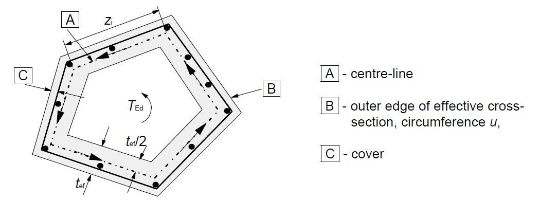
In Eurocode 2, the shear stress in a wall of a section subject to a pure torsional moment may be calculated from:
τt,itef,i = TEd/2Ak
The shear force VEd,i in a wall i due to torsion is given by:
VEd,i = τt,itef,izi
where;
TEd is the applied design torsion
Ak is the area enclosed by the centre-lines of the connecting walls, including inner hollow areas.
τt,i is the torsional shear stress in wall i
tef,i is the effective wall thickness. It may be taken as A/u, but should not be taken as less than twice the distance between edge and centre of the longitudinal reinforcement. For hollow sections the real thickness is an upper limit
A is the total area of the cross-section within the outer circumference, including inner hollow areas
u is the outer circumference of the cross-section
zi is the side length of wall i defined by the distance between the intersection points with the adjacent walls
The required cross-sectional area of the longitudinal reinforcement for torsion ΣAsl may be calculated from Expression (6.28) of EC2:
ΣAsl/fyd = TEdcotθ/2Ak
where;
uk is the perimeter of the area Ak
fyd is the design yield stress of the longitudinal reinforcement Asl
θ is the angle of compression struts
According to clause 6.3.2(4) of EC2, the maximum resistance of a member subjected to torsion and shear is limited by the capacity of the concrete struts. In order not to exceed this resistance the following condition should be satisfied:
TEd/TRd,max + VEd/VRd,max ≤ 1.0 (Equation 6.29, EC2)
where:
TEd is the design torsional moment
VEd is the design transverse force
TRd,max is the design torsional resistance moment = TRd,max = 2ναcwfcdAktef,isinθcosθ
VRd,max is the maximum design shear resistance according to Expressions (6.9) of EC2
Worked Example
Carry out a full torsional design of a rectangular reinforced concrete (RC) beam subjected to an ultimate torsional moment of 55 kNm, and shear force of 225 kN. The section is 600 x 400 mm, and reinforcement of 4H25 (As,prov = 1964 mm2) has been provided to resist the bending moment. (fck = 28 N/mm2; fyk = 500 N/mm2)
Solution
Concrete strength class; C28/35 ×γα
Characteristic compressive cylinder strength;fck = 28 N/mm2
Partial factor for concrete -Table 2.1N; γC = 1.50
Compression chord stress coefficient – cl.6.2.3(3); αcw = 1.00
Compressive strength coefficient – cl.3.1.6(1); αcc = 0.85
Design compressive concrete strength – exp.3.15; fcd = αcc × fck/γC = 15.9 N/mm2
Compressive strength coefficient – cl.3.1.6(1); αccw = 1.00
Design compressive concrete strength – exp.3.15; fcwd = αccw × fck/γC = 18.7 N/mm2
Tensile strength coefficient – cl.3.1.6(2); αct = 1.00
Mean value of axial strength of conc. – cl.3.1.6(2); fctm = 0.3 N/mm2 × (fck)2/3 = 2.77 N/mm2
Characteristic axial strength of conc. (5% factile); fctk,0.05 = 0.7 × fctm = 1.94 N/mm2
Design axial strength of concrete; fct,d = act × fctk,0.05/γC = 1.29 N/mm2
Reinforcement details
Characteristic yield strength of reinforcement; fyk = 500 N/mm2
Partial factor for reinforcing steel – Table 2.1N; γS = 1.15
Design yield strength of reinforcement; fyd = fyk/γS = 435 N/mm2
Beam dimensions
Section width; b = 400 mm
Section depth; h = 600 mm
Design forces
Maximum design torsional moment; TEd,max = 55.0 kNm
Maximum design shear force; VEd,max = 225.0 kN
Area of design longitudinal reinforcement; Asl = 1964 mm2
Effective depth to outer layer; d = 450 mm
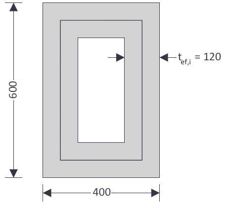
Torsional resistance (Section 6.3, EC2)
Effective thickness of walls – cl.6.3.2(1); tef,i = (b × h) / (2 × (b + h)) = 120 mm
Area enclosed by centre lines of walls – cl.6.3.2(1); Ak = (b – tef,i) × (h – tef,i) = 134400 mm2
Perimeter – cl.6.3.2(3); Uk = 2 × ((b – tef,i) + (h – tef,i)) = 1520 mm
Strength reduction factor; v1 = 0.6 × (1 – fck / 250 N/mm2) = 0.533
Design shear stress; vt,Ed = VEd,max / (b × d) = 1.250 N/mm2
Torsional shear stress in wall – exp.6.26; tt,Ed = TEd,max / (2 × Ak × tef,i) = 1.705 N/mm2
Concrete strut angle;qt = min[45°, max(0.5 × Asin(min(2 × (vt,Ed / 0.9 + tt,Ed) / (αcw × fcwd × v1), 1)), 21.8°)] = 21.8°
Max design value of torsional resist. mnt – exp 6.30; TRd,max = 2 × v1 × αcw × fcd × Ak × tef,i × sin(qt) × cos(qt) = 94.0 kNm
Max design shear force – exp.6.9; VRdt,max = acw × b × 0.9 × d × v1 × fcwd / (cot(qt) + tan(qt)) = 555.6 kN
Interaction formulae – exp.6.29; TEd,max / TRd,max + VEd,max / VRdt,max = 0.990
PASS – concrete section is adequate
Torsional and shear resistance of the concrete alone
Maximum torsional resist moment with no shear reinf. – cl.6.3.2(5); TRd,c = 2 × Ak × fct,d × tef,i = 41.6 kNm
Shear resistance constant – cl.6.2.2; CRd,c = 0.18/γC = 0.120
Reinforcement ratio – cl.6.2.2; rl = min(Asl/(d × b), 0.02) = 0.011
Effective depth factor – cl.6.2.2; kv = min(1 + √(200mm/d), 2) = 1.667
Minimum shear stress; vmin = 0.035 N/mm2 × kv3/2 × (fck / 1N/mm2)0.5 = 0.4 N/mm2
Design value for shear resistance – exp.6.2.a; VRd,c = max(CRd,c × kv × 1N/mm2 × (100 × rl × fck/1N/mm2)1/3 × b × d, vmin × b × d) = 112.5 kN
Interaction formulae – exp.6.31; TEd,max / TRd,c + VEd,max / VRd,c = 3.320
Therefore, additional reinforcement required
Required torsional reinforcement
Required area of add. long. reinf. for torsion (6.28); Asl,req = TEd,max × Uk × cot(qt) / (2 × Ak × fyd) = 1788 mm2
Provide 10Y16 side bars (5 on each face) for torsion (Asprov = 2010 mm2)
The longitudinal bars should be arranged so there is at least one bar at each corner with the other spaced around the periphery of the links at a spacing of 350mm or less (cl.9.2.3(4))
Required shear reinforcement for torsion (one leg); Asw,req = TEd,max / (2 × Ak × fyd × cot(qt)) = 188 mm2/m
Maximum spacing for torsion shear reinforcement; sw,max = min(Uk/8, b, h) = 190 mm
Provide 2 legs H10@175 c/c as torsion/shear reinforcement
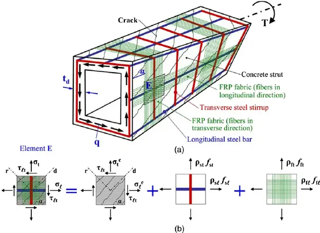
[Featured Image Credit] Chai H.K., Majeed A.A., Allawi A.A (2015): Torsional Analysis of Multicell Concrete Box Girders Strengthened with CFRP Using a Modified Softened Truss Model. ASCE Journal of Bridge Engineering, 20(8) https://doi.org/10.1061/(ASCE)BE.1943-5592.0000621
To download this article in PDF format, click HERE

