Moving traffic is the major live load (variable action) on bridge decks. In the design of bridges, it is very important to consider the global and local effects of moving traffic loads on the bridge. While global effects can be used to distribute traffic wheel load to the girders (in the case of beam and slab bridges), local verification is very important in the design of deck slabs especially for bending moment and shear. In this article, we are going to show how to distribute single wheel load to bridge deck slabs.
In BS 5400, single HA load (with a value of 100 kN) is normally used for all types of local effects verification. This load is normally assumed to act on a square contact area of 300 mm x 300 mm to give a pressure of 1.11 N/mm2 on the surface where it is acting. For 45 units of HB load, a single wheel load of 112.5 kN can be considered where necessary.
In EN 1991-2 (Eurocode specification for bridges), the local wheel load is represented by Load Model 2 (LM2) which consists of a single axle load with a magnitude of 400 kN (inclusive of the dynamic amplification factor). The single axle consists of two wheels (200 kN each) spaced at a distance of 2m (centre to centre). This load model is intended to be used for local verification only and should be considered alone on the longitudinal axis of thebridge. Unless otherwise specificied, each wheel is assummed to act on a rectangular area of 600 x 350 mm.
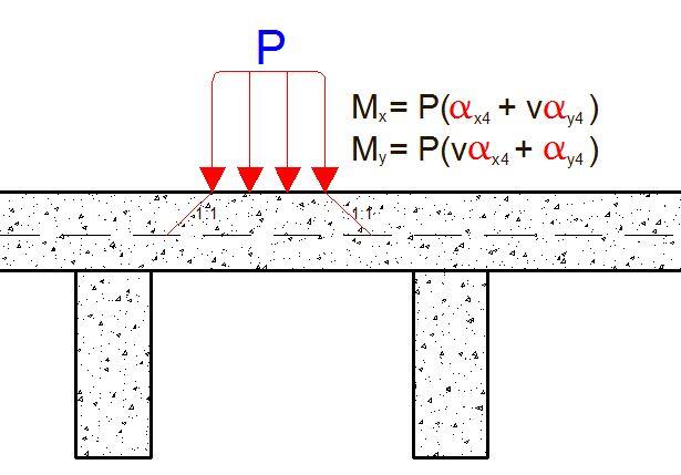
To apply single wheel load on bridge decks for local verification, the wheel load is placed at the most adverse location on the bridge deck, and the contact pressure distributed to the neutral axis of the bridge deck. For all practical purposes, the neutral axis is normally taken at the mid-section of the bridge deck. For distribution of wheel load through concrete deck slabs, a ratio of 1:1 is normally adopted (dispersal angle of 45 degrees), while for distribution through asphalt surfacing, a dispersal ratio of 1:2 is normally adopted.
When the contact pressure has been obtained (together) with the dimensions of the contact area, the effects of the wheel load on the slab can be assessed using any suitable method. For manual analysis, Pigeaud’s curve can be used to obtain the design bending moments. For finite element analysis, the contact pressure can be applied as a patch load (partially distributed load) on a slab surface.
To show how this is done, let us consider a worked example.
Worked Example
Obtain the design moments in an interior panel of deck slab of the bridge system shown below due to the effect of a single HA wheel load on the bridge deck. The deck slab is overlain with a 75mm thick asphalt surfacing.
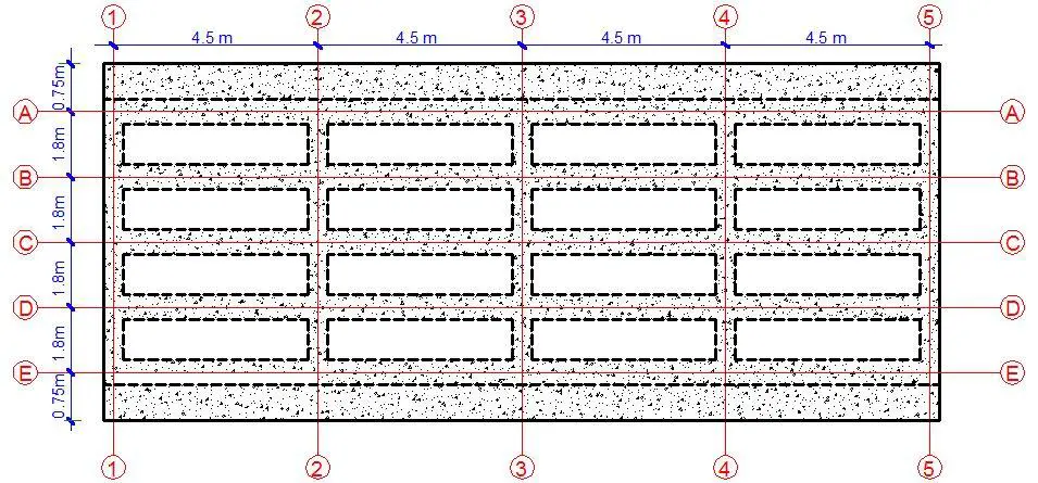
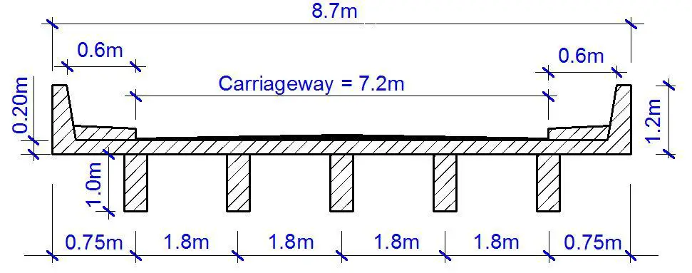
The dimensions of an interior panel of the bridge deck are as follows;
Length (ly) = 4.5 m
Width (lx) = 1.8
Support condition: Continuous over all supports
Design wheel load = 100 kN
Contact area = 300 x 300 mm
The contact pressure = 100 kN/(0.3 x 0.3)m = 1111.11 kN/m2
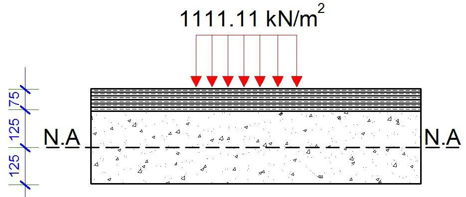
A 2(V):1(H) load distribution through the 75 mm thick asphalt to the surface of the deck slab will give a pressure of 711.11 kN/m2 acting on a square contact area of 375 x 375 mm.
A further 1:1 load distribution from the surface of the concrete deck slab to the neutral axis will give a pressure of 256 kN/m2 acting on a square contact area of 625 x 625 mm.
Therefore;
ax = ay = 625 mm
To enable us use the Pigeaud’s curves;
k = ly/lx = 4.5/1.8 = 2.5
ax/lx = 0.625/1.8 = 0.347
ay/ly = 0.625/4.5 =0.138
From Table 55 of Reynolds and Steedman (10th Edition),
αx4 = 0.169
αy4 = 0.0964
Poisson’s ration v = 0.2
Transverse bending moment Mx = F(αx4 + vαy4) = 100 x (0.169 + 0.2 x 0.0964) = 18.828 kNm/m
Longitudinal bending moment My = F(vαx4 + αy4) = 100 x (0.2 x 0.169 + 0.0964) = 13.02 kNm/m
Taking account of suggested allowances for continuity in the transverse direction;
Mx1 = -0.25Mx = 0.25 x 18.828 = -4.707 kNm
These are therefore the bending moments due to the HA wheel load on the deck slab

