Precast concrete columns are reinforced concrete columns that are cast and cured on the ground before being hoisted up and installed in their desired positions. Just like in-situ columns, precast columns are capable of resisting shear, axial force, and bending moment, however, careful attention must be paid to their connection details. The design of precast concrete columns involves the provision of adequate member size, reinforcement, and connection details to satisfy internal stresses due to externally applied loads, second-order effects, and lifting.
Different connection conditions can be adopted by different manufacturers. The foundation connection of a precast column may be achieved by allowing reinforcement bars to project from the column which is then passed through established sleeves before being filled with concrete grout. Alternatively, a base plate can be connected to the column which is then installed in position on a concrete base using bolts and nuts.
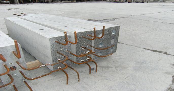
Precast columns may have corbels or nibs for supporting the beams. Alternatively, precast beam-column connections can be made using dowels or mechanical couplers.
Precast concrete columns have the following advantages over in-situ concrete construction;
- Increased speed in construction since production of precast elements can commence ahead of time
- Greater flexibility in project management and site planning due to off-site production capacity
- Improved and higher quality of concrete, dimensions, and surface finishes
- Reduction in site labour
- Reduction in formwork requirement
- Less wastage of materials
The design of precast reinforced concrete columns is carried out by a structural engineer and involves the following steps;
- Confirm all dimensions and tolerances of the column and other members.
- Analyse the structure to obtain the design bending moments, axial, and shear force
- Check for column slenderness
- Obtain the final design moments taking into account imperfections and second-order effects (if applicable)
- Provide reinforcements to satisfy bending and axial force
- Check for biaxial bending
- Check for shear
- Check that reinforcement provided satisfies bending and shear due to factory lifting
- Check that reinforcement provided satisfies bending and shear due to site pitching
- Design the connections
- Detail the column as appropriate
Worked Example on the Design of Precast Columns | EN 1992-1:2004
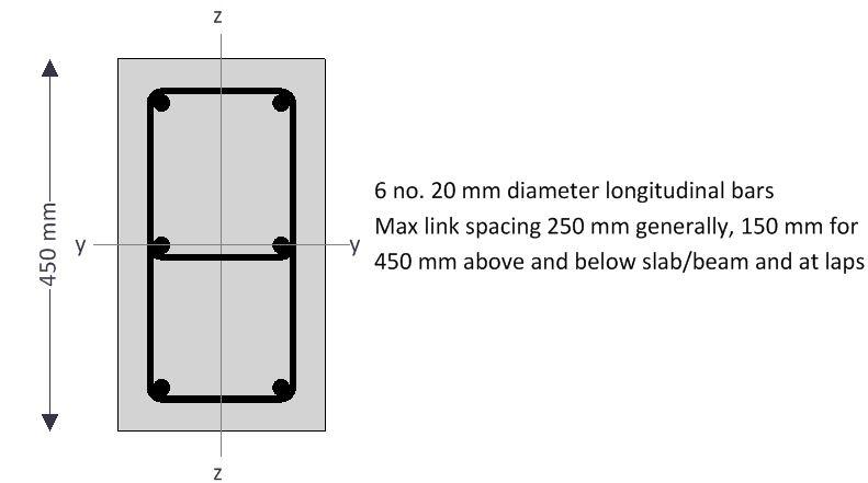
Check the capacity of a 4.5m high 450 x 250 mm precast column to resist the action effects given below. The column is reinforced with 6 numbers of H20 mm bars. fck = 35 N/mm2; fyk = 500 N/mm2; Concrete cover = 35 mm. The design has been executed using Tekla Tedds software.
Axial load and bending moments from frame analysis
Design axial load; NEd = 1350.0 kN
Moment about y-axis at top; Mtop,y = 55.0 kNm
Moment about y-axis at bottom; Mbtm,y = 22.0 kNm
Moment about z-axis at top; Mtop,z = 11.4 kNm
Moment about z-axis at bottom; Mbtm,z = 5.5 kNm
Column geometry
Overall depth (perpendicular to y-axis); h = 450 mm
Overall breadth (perpendicular to z-axis); b = 250; mm
Stability in the z-direction; Braced
Stability in the y-direction; Braced
Concrete details
Concrete strength class; C30/37
Partial safety factor for concrete (2.4.2.4(1)); γC = 1.50
Coefficient αcc (3.1.6(1)); αcc = 0.85
Maximum aggregate size; dg = 20 mm
Reinforcement details
Nominal cover to links; cnom = 35 mm
Longitudinal bar diameter; ϕ = 20 mm
Link diameter; ϕv = 8 mm
Total number of longitudinal bars; N = 6
No. of bars per face parallel to y-axis; Ny = 2
No. of bars per face parallel to z axis; Nz = ;3
Area of longitudinal reinforcement; As = N × π × ϕ2 / 4 = 1885 mm2
Characteristic yield strength; fyk = 500 N/mm2
Partial safety factor for reinft (2.4.2.4(1)); γS = 1.15
Es = 200000 MPa
Column effective lengths
Effective length for buckling about y-axis; l0y = 3500 mm
Effective length for buckling about z-axis; l0z = 3900 mm
Effective depths of bars for bending about y-axis
Area per bar; Abar = π × ϕ2/4 = 314 mm2
Spacing of bars in faces parallel to z-axis (centre to centre);
sz = h – 2 × (cnom + ϕv) – ϕ)/ (Nz – 1) = 172 mm
Layer 1 (in tension face); dy1 = h – cnom – ϕv – ϕ/2 = 397 mm
Layer 2; dy2 = dy1 – sz = 225 mm
Layer 3; dy3 = dy2 – sz = 53 mm
2nd moment of area of reinforcement about y axis;
Isy = 2 × Abar × [Ny × (dy1 – h/2)2] = 3718 cm4
Radius of gyration of reinforcement about y-axis; isy = √(Isy/As) = 140 mm
Effective depth about y axis (5.8.8.3(2)); dy = h/2 + isy = 365 mm
Effective depths of bars for bending about z-axis
Area of per bar; Abar = π × ϕ2 / 4 = 314 mm2
Spacing of bars in faces parallel to y axis (c/c); sy = (b – 2 × (cnom + ϕv) – ϕ) / (Ny – 1) = 144 mm
Layer 1 (in tension face); dz1 = b – cnom – ϕv – ϕ/2 = 197 mm
Layer 2; dz2 = dz1 – sy = 53 mm
Effective depth about z axis; dz = dz1 = 197 mm
Column slenderness about y-axis
Radius of gyration; iy = h/√(12) = 13.0 cm
Slenderness ratio (5.8.3.2(1)); ly = l0y / iy = 26.9
Column slenderness about z-axis
Radius of gyration; iz = b/√(12) = 7.2 cm
Slenderness ratio (5.8.3.2(1));lz = l0z / iz = 54.0
Design bending moments
Frame analysis moments about y axis combined with moments due to imperfections (cl. 5.2 & 6.1(4))
Eccentricity due to geometric imperfections (y axis); eiy = l0y /400 = 8.8 mm
Min end moment about y-axis; M01y = min(|Mtopy|, |Mbtmy|) + eiyNEd = 33.8 kNm
Max end moment about y-axis; M02y = max(|Mtopy|, |Mbtmy|) + eiyNEd = 66.8 kNm
Slenderness limit for buckling about y axis (cl. 5.8.3.1)
A = 0.7
Mechanical reinforcement ratio; ω = As × fyd / (Ac × fcd) = 0.429
Factor B; B = √(1 + 2ω) = 1.363
Moment ratio; rmy = M01y / M02y = 0.506
Factor C; Cy = 1.7 – rmy = 1.194
Relative normal force; n = NEd / (Ac × fcd) = 0.706
Slenderness limit; llimy = 20 × A × B × Cy / √(n) = 27.1
ly < llimy – Second order effects may be ignored
Frame analysis moments about z-axis combined with moments due to imperfections (cl. 5.2 & 6.1(4))
Ecc. due to geometric imperfections (z axis); eiz = l0z /400 = 9.8 mm
Min end moment about z axis; M01,z = min(|Mtopz|, |Mbtmz|) + eizNEd = 18.7 kNm
Max end moment about z axis; M02,z = max(|Mtopz|, |Mbtmz|) + eizNEd = 24.5 kNm
Slenderness limit for buckling about y-axis (cl. 5.8.3.1)
A = 0.7
Mechanical reinforcement ratio; w = As × fyd / (Ac × fcd) = 0.429
Factor B; B = √(1 + 2ω) = 1.363
Moment ratio; rmz = 1.000
Factor C; Cz = 1.7 – rmz = 0.700
Relative normal force; n = NEd / (Ac × fcd) = 0.706
Slenderness limit; llimz = 20 × A × B × Cz / √(n) = 15.9
lz > llimz – Second order effects must be considered
Design bending moments (cl. 6.1(4))
Design moment about y axis; MEdy = max(M02y, NEd × max(h/30, 20 mm)) = 66.8 kNm
Local second order bending moment about z-axis (cl. 5.8.8.2 & 5.8.8.3)
Relative humidity of ambient environment; RH = 50 %
Column perimeter in contact with atmosphere; u = 1400 mm
Age of concrete at loading; t0 = 28 day
Parameter nu; nu = 1 + w = 1.429
nbal = 0.4
Approx value of n at max moment of resistance; nbal = 0.4
Axial load correction factor; Kr = min(1.0 , (nu – n) / (nu – nbal)) = 0.703
Reinforcement design strain; εyd = fyd/Es = 0.00217
Basic curvature; curvebasic_z = εyd / (0.45 × dz) = 0.0000245 mm-1
Notional size of column; h0 = 2 × Ac / u = 161 mm
Factor a1 (Annex B.1(1)); a1 = (35 MPa / fcm)0.7 = 0.944
Factor a2 (Annex B.1(1)); a2 = (35 MPa / fcm)0.2 = 0.984
Relative humidity factor (Annex B.1(1));
ϕRH = [1 + ((1 – RH/100%) / (0.1 mm-1/3 × (h0)1/3)) × a1] × a2 = 1.838
Concrete strength factor (Annex B.1(1));
βfcm = 16.8 × (1 MPa)1/2 / √(fcm) = 2.725
Concrete age factor (Annex B.1(1));
βt0 = 1 / (0.1 + (t0 / 1 day)0.2) = 0.488
Notional creep coefficient (Annex B.1(1));
ϕ0 = ϕRH × βfcm × βt0 = 2.446
Final creep development factor; (at t = ∞); βc∞ = 1.0
Final creep coefficient (Annex B.1(1));ϕ∞ = ϕ0 × βc∞ = 2.446
Ratio of SLS to ULS moments rMz (say) = 0.80
Effective creep ratio (5.8.4(2)); fefz = f∞ × rMz = 1.957
Factor β; βz = 0.35 + fck / 200 MPa – lz / 150 = 0.140
Creep factor; Kϕz = max(1.0, 1 + βz × ϕefz) = 1.273
Modified curvature; curvemod_z = Kr × Kϕz × curvebasic_z = 0.0000219 mm-1
Curvature distribution factor; c = 10
Deflection; e2z = curvemod_z × l0z2/c = 33.4 mm
Nominal 2nd order moment;
M2z = NEd × e2z = 45.1 kNm
Design bending moment about z-axis (cl. 5.8.8.2 & 6.1(4))
Equivalent moment from frame analysis;
M0ez = max(0.6 × M02z + 0.4 × M01z, 0.4 × M02z) = 22.2 kNm
Design moment;
MEdz = max(M02z, M0ez + M2z, M01z + 0.5 × M2z, NEd × max(b/30, 20 mm))
MEdz = 67.2 kNm
Moment capacity about y-axis with axial load (1350.0 kN)
Moment of resistance of concrete
By iteration:
Position of neutral axis; y = 317.8 mm
Concrete compression force (3.1.7(3));
Fyc = h × fcd × min(lsb × y, h) × b = 1080.6 kN
Moment of resistance;
MRdyc = Fyc × [h / 2 – (min(lsb × y, h)) / 2] = 105.8 kNm
Moment of resistance of reinforcement
Strain in layer 1; εy1 = εcu3 × (1 – dy1/y) = -0.00087
Stress in layer 1; σy1 = max(-1 × fyd, Es × εy1) = -174.4 N/mm2
Force in layer 1; Fy1 = Ny × Abar × σy1 = -109.6 kN
Moment of resistance of layer 1; MRdy1 = Fy1 × (h/2 – dy1) = 18.8 kNm
Strain in layer 2; εy2 = εcu3 × (1 – dy2 / y) = 0.00102
Stress in layer 2; σy2 = min(fyd, Es × εy2) – h × fcd = 187.4 N/mm2
Force in layer 2; Fy2 = 2 × Abar × σy2 = 117.8 kN
Moment of resistance of layer 2; MRdy2 = Fy2 × (h/2 – dy2) = 0.0 kNm
Strain in layer 3; εy3 = εcu3 × (1 – dy3/y) = 0.00292
Stress in layer 3; σy3 = min(fyd, Es × εy3) – h × fcd = 417.8 N/mm2
Force in layer 3; Fy3 = Ny × Abar × σy3 = 262.5 kN
Moment of resistance of layer 3; MRdy3 = Fy3 × (h/2 – dy3) = 45.2 kNm
Resultant concrete/steel force; Fy = 1351.2 kN
PASS – This is within half of one percent of the applied axial load
Combined moment of resistance
Moment of resistance about y axis; MRdy = 169.8 kNm
PASS – The moment capacity about the y axis exceeds the design bending moment
Moment capacity about z-axis with axial load (1350.0 kN)
Moment of resistance of concrete
By iteration, position of neutral axis; z = 171.9 mm
Concrete compression force (3.1.7(3)); Fzc = h × fcd × min(lsb × z, b) × h = 1051.9 kN
Moment of resistance; MRdzc = Fzc × [b / 2 – (min(lsb × z, b)) / 2] = 59.2 kNm
Moment of resistance of reinforcement
Strain in layer 1; εz1 = εcu3 × (1 – dz1 / z) = -0.00051
Stress in layer 1; σz1 = max(-1 × fyd, Es × εz1) = -102.3 N/mm2
Force in layer 1; Fz1 = Nz × Abar × σz1 = -96.4 kN
Moment of resistance of layer 1; MRdz1 = Fz1 × (b / 2 – dz1) = 6.9 kNm
Strain in layer 2; εz2 = εcu3 × (1 – dz2/z) = 0.00242
Stress in layer 2; σz2 = min(fyd, Es × εz2) – h × fcd = 417.8 N/mm2
Force in layer 2; Fz2 = Nz × Abar × σz2 = 393.8 kN
Moment of resistance of layer 2; MRdz2 = Fz2 × (b/2 – dz2) = 28.4 kNm
Resultant concrete/steel force; Fz = 1349.2 kN
PASS – This is within half of one percent of the applied axial load
Combined moment of resistance
Moment of resistance about z-axis; MRdz = 94.5 kNm
PASS – The moment capacity about the z-axis exceeds the design bending moment
Biaxial bending
Determine if a biaxial bending check is required (5.8.9(3))
Ratio of column slenderness ratios; ratiol = max(ly, lz) / min(ly, lz) = 2.01
Eccentricity in direction of y axis; ey = MEdz/NEd = 49.8 mm
Eccentricity in direction of z axis; ez = MEdy/NEd = 49.5 mm
Equivalent depth; heq = iy × √(12) = 450 mm
Equivalent width; beq = iz × √(12) = 250 mm
Relative eccentricity in direction of y-axis; erel_y = ey/beq = 0.199
Relative eccentricity in direction of z-axis; erel_z = ez/heq = 0.110
Ratio of relative eccentricities;
ratioe = min(erel_y, erel_z)/max(erel_y, erel_z) = 0.552
ratiol > 2 and ratioe > 0.2
Therefore, biaxial bending check is required.
Biaxial bending (5.8.9(4))
Design axial resistance of section; NRd = (Ac × fcd) + (As × fyd) = 2732.0 kN
Ratio of applied to resistance axial loads; ratioN = NEd / NRd = 0.494
Exponent a; a = 1.33
Biaxial bending utilisation; UF = (MEdy/MRdy)a + (MEdz/MRdz)a = 0.926 (Okay)
Shear
Design shear force; VEd = VEd,y = 25.8 kN
CRd,c = 0.18/γC = 0.12
Tension reinforcement; Asl = Nz × π × ϕ2/4 = 942 mm2
Depth of tension reinforcement; dv = dz1 = 197 mm
kshear = min(1 + (200 mm / dv)0.5, 2) = 2.000
Width of the cross section in tensile area; bw = h = 450 mm
Longitudinal reinforcement ratio; rl = min(Asl/(bw × dv), 0.02) = 0.01063
Axial pressure in cross-section; σcp = min(NEd/Ac, 0.2 × fcd) = 3.40 N/mm2
vmin = 0.035 N0.5/mm × kshear3/2 × fck1/2 = 0.54 N/mm2
k1,shear = 0.15
Design shear resistance – exp. 6.2 a & b;
VRd,c = max(CRd,c × kshear × (100 N2/mm4 × rl × fck)1/3, vmin) × bw × dv + k1,shear × σcp × bw × dv = 112.7 kN
VEd / VRd,c = 0.23
PASS – Design shear resistance exceeds design shear force
Factory Lifting Check

Precast element details
Total length of column; Lelement = 4500 mm
Distance between lifting points; Llift = 2500 mm
Lifting load coefficient; flifting = 1.50
Permanent load factor; γG = 1.35
Formwork adhesion force; qformwork = 2.0 kN/m2
Self weight of precast element; wself_precast = b × h × ρconc × gacc + qformwork × b = 3.3 kN/m
Lifting check (positive moment)
Design bending moment; M = γG × flifting × (wself_precast × Llift2 /8 – wself_precast × ((Lelement – Llift) / 2)2/2) = 1.9 kNm
Effective depth of tension reinforcement; d = 397 mm
Redistribution ratio; d = 1.000
K = M / (b × d2 × fck) = 0.002
No compression reinforcement is required
Lever arm; z = min(0.5 × d × (1 + (1 – 2 × K / (h × acc / γC))0.5), 0.95 × d) = 377 mm
Depth of neutral axis; x = 2 × (d – z)/lsb = 50 mm
Area of tension reinforcement required; As,pos = M / (fyd × z) = 11 mm2
Tension reinforcement provided; 2H20 mm (As,prov = 628 mm2)
Minimum area of reinforcement – exp.9.1N; As,min = max(0.26 × fctm/fyk, 0.0013) × b × d = 149 mm2
Maximum area of reinforcement – cl.9.2.1(3); As,max = 0.04 × b × h = 4500 mm2
Required area of reinforcement; As,req = 149 mm2
As,req / As,prov = 0.24 (okay)
Lifting check (negative moment)
Design bending moment; M = γG × flifting × wself_precast × ((Lelement – Llift) / 2)2 / 2 = 3.3 kNm
Effective depth of tension reinforcement; d = 397 mm
Redistribution ratio; d = 1.000
K = M / (b × d2 × fck) = 0.003
Area of tension reinforcement required; As,neg = M / (fyd × z) = 20 mm2
Tension reinforcement provided; 2H20 mm (As,prov = 628 mm2)
Minimum area of reinforcement – exp.9.1N; As,min = max(0.26 × fctm/fyk, 0.0013) × b × d = 149 mm2
Maximum area of reinforcement – cl.9.2.1(3); As,max = 0.04 × b × h = 4500 mm2
Required area of reinforcement; As,req = 149 mm2
As,req / As,prov = 0.24 (Okay)
Lifting check (Shear)
Design shear force at critical shear plane;
VEd = γG × flifting × wself_precast × max(Llift / 2, (Lelement – Llift) / 2) = 8.2 kN
CRd,c = 0.18/γC = 0.12
Tension reinforcement; Asl = Ny × π × ϕ2 / 4 = 628 mm2
Depth of tension reinforcement; dv = dy1 = 397 mm
kshear = min(1 + (200 mm / dv)0.5, 2) = 1.710
Width of the cross section in tensile area; bw = b = 250 mm
Longitudinal reinforcement ratio; ρl = min(Asl / (bw × dv), 0.02) = 0.00633
vmin = 0.035 N0.5/mm × kshear3/2 × fck1/2 = 0.43 N/mm2
Design shear resistance – exp. 6.2 a & b;
VRd,c = max(CRd,c × kshear × (100 N2/mm4 × ρl × fck)1/3, vmin) × bw × dv
VRd,c = 54.3 kN
VEd / VRd,c = 0.15 (This is okay)
On-site Pitching Check

Precast element details
Total length of column; Lelement = 4500 mm
Distance to the pitching point; Lpitch = 1800 mm
Distance from pitching point to end of column;Lend = 2700 mm
Lifting load coefficient; fpitching = 1.25
Permanent load factor; gG = 1.35
Self weight of precast element; wself_precast = b × h × ρconc × gacc = 2.8 kN/m
Lifting check (positive moment)
Design bending moment (at 3750 mm);
M = gG × fpitching × wself_precast × Lelement2 / (2 × Lend) × (0.25 × Lelement2/Lend – Lpitch) = 1.3 kNm
Effective depth of tension reinforcement; d = 397 mm
Redistribution ratio; d = 1.000
K = M / (b × d2 × fck) = 0.001
Area of tension reinforcement required; As,pos = M / (fyd × z) = 8 mm2
Tension reinforcement provided; 2H20 mm (As,prov = 628 mm2)
Minimum area of reinforcement – exp.9.1N; As,min = max(0.26 × fctm/fyk, 0.0013) × b × d = 149 mm2
Maximum area of reinforcement – cl.9.2.1(3); As,max = 0.04 × b × h = 4500 mm2
Required area of reinforcement; As,req = 149 mm2
As,req / As,prov = 0.24 (Okay)
Lifting check (negative moment)
Design bending moment; M = gG × fpitching × wself_precast × Lpitch 2 / 2 = 7.5 kNm
Effective depth of tension reinforcement; d = 397 mm
Redistribution ratio; d = 1.000
K = M / (b × d2 × fck) = 0.006
Area of tension reinforcement required; As,neg = M / (fyd × z) = 46 mm2
Tension reinforcement provided; 2H20 mm (As,prov = 628 mm2)
Minimum area of reinforcement – exp.9.1N; As,min = max(0.26 × fctm/fyk, 0.0013) × b × d = 149 mm2
Maximum area of reinforcement – cl.9.2.1(3); As,max = 0.04 × b × h = 4500 mm2
Required area of reinforcement; As,req = 149 mm2
As,req / As,prov = 0.24 (Okay)
Lifting check (Shear)
Design shear force at critical shear plane;
VEd = gG × fpitching × wself_precast × max(Lpitch, abs(Lelement – 0.5 × Lelement2 / Lend), abs(Lend – (Lelement – 0.5 × Lelement2 / Lend))) = 9.1 kN
CRd,c = 0.18/γC = 0.12
Tension reinforcement; Asl = Ny × π × ϕ2 / 4 = 628 mm2
Depth of tension reinforcement; dv = dy1 = 397 mm
kshear = min(1 + (200 mm / dv)0.5, 2) = 1.710
Width of the cross section in tensile area; bw = b = 250 mm
Longitudinal reinforcement ratio; ρl = min(Asl / (bw × dv), 0.02) = 0.00633
vmin = 0.035 N0.5/mm × kshear3/2 × fck1/2 = 0.43 N/mm2
Design shear resistance – exp. 6.2 a & b;
VRd,c = max(CRd,c × kshear × (100 N2/mm4 × ρl × fck)1/3, vmin) × bw × dv
VRd,c = 54.3 kN
VEd / VRd,c = 0.17 (Okay)
Connection
The connection of the column can be designed and checked depending on the method adopted.

