Reinforced concrete (R.C.) slabs are plate elements used to form the floors of buildings. In a typical reinforced concrete building, reinforcement bars arranged as mats are incorporated into a concrete plate of minimum thickness 125 mm to form a reinforced concrete solid slab. The provision of adequate reinforcement, slab thickness, and proper detailing to satisfy ultimate and serviceability limit state requirements forms the basis of the design of reinforced concrete (R.C.) slab. Satisfying other requirements such as durability, fire resistance, etc are also necessary.
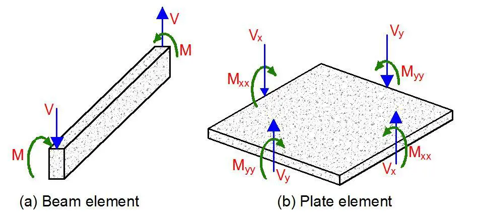
Floor slabs are usually subjected to uniformly distributed loads, partially distributed loads, line loads, or concentrated loads in the transverse direction. A beam is similar to a slab in so many ways but there are fundamental differences in behaviour and stress distribution of the two elements. While a beam is generically a one-dimensional element, a plate is a two-dimensional element. Due to the two-dimensional nature of a slab, it is subjected not only to bending moments Mxx and Myy and shear forces Vx and Vy but also to twisting moments Mxy on all the four faces.
Types of Reinforced Concrete Slabs
A monolithic reinforced concrete slab is essentially a statically indeterminate structure. For a slab of a given shape and support conditions, the distribution of shear forces, bending, and twisting moments in the slab due to externally applied loads cannot be determined easily. The column layout in a monolithic reinforced concrete structure often forms a rectangular grid. Continuous beams may be provided in one direction or two orthogonal directions, to support slabs that may be solid or ribbed in cross-section. Alternatively, slabs can be supported directly on columns to form flat slabs.
Slabs may be simply supported or continuous over one or more supports and are classified according to the method of support as follows:
- One-way spanning slab between beams or walls
- Two-way spanning slab between the support beams or walls
- Flat slabs carried on columns and edge beams or walls with no interior beams
- Ribbed slab transferring slab load to beams and walls in one direction
- Waffle slab transferring slab load to beams and slabs in two direction
One-way Spanning Solid Slabs
Clause 5.3.1(5) of EN 1992-1-1:2004 suggests that a slab subjected dominantly to uniformly distributed loads may be considered as one-way spanning if either:
- It possesses two free (unsupported) and sensibly parallel edges.
- It is the central part of a sensibly rectangular slab supported on four edges with a ratio of longer (Ly) to shorter span (Lx) greater than 2.
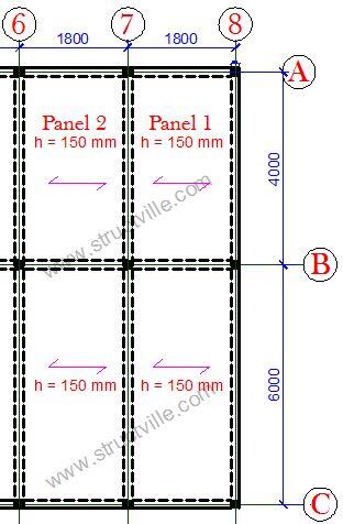
In other words, when beams are provided in one parallel direction only, the slab is a one-way slab. Furthermore, if the longer side of a slab panel exceeds twice the shorter side, the slab is generally designed as a one-way slab, but that does not mean that the slab is transmitting load in one direction only.
One-way slabs may be simply supported or continuous. For one-way slabs supported on two opposite sides, the bending moments are calculated in the same way as for beams. Continuity across a beam is treated as fixed support. In detailing, if a slab is assumed to be simply supported at an end support, it is advisable to provide reinforcement for a probable negative bending moment due to the monolithic construction of beams and slabs (Reynolds and Steedman, 2005).

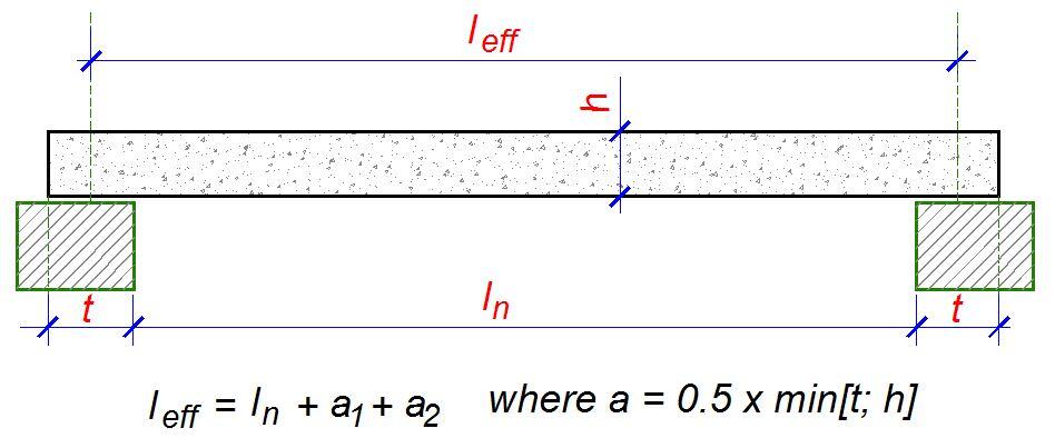
The effective span for one-way slabs is the same as that of beams. If ln is the clear span (distance between faces of supports), the effective span leff is given by;
leff = ln + a1 + a2
One-way slabs should be designed to resist the most unfavourable arrangement of loads. In clause 5.1.3 of Eurocode 2, the following two loading arrangements are recommended for buildings.
- Alternate spans carrying (γGGk + γQQk) other spans carrying only γGGk.
- Any two adjacent spans carrying (γGGk + γQQk). All other spans carrying only γGGk
Steps in the design of a one-way slab
The steps in the design of a slab are as follows;
- Determine the design life of the structure
- Choose a slab thickness determined using deflection requirements, experience, or otherwise
- Establish the durability requirements, fire resistance, and adequate concrete cover
- Calculate and apply the loads on the slab comprising of the dead and imposed loads
- Apply the appropriate load combination
- Idealise each slab element and analyse to determine the critical design moments MEd and shear forces VEd
- Carry out the flexural design
- Check the deflection
- Check the shear capacity
- Check bar spacing and cracking
For the flexural design of slabs, determine k from;
k = MEd/(fckbd2)
If k < 0.167, no compression reinforcement is required, and you can calculate the lever arm;
z = d[0.5 + √(0.25 – 0.882k)]
The area of reinforcement required is given by;
As1 = MEd/(0.87fykz)
(a) Concrete cover
The nominal concrete cover in slabs is expected to satisfy the requirement;
Cnom = Cmin + ∆c,dev
Cmin is expected to satisfy the requirement for durability, fire resistance, and bond, while ∆c,dev is the allowance made for construction deviation (usually 10 mm). The minimum cover for bond should not be less than the bar diameter. For a one-way slab to have a fire rating of one hour (REI 60), the minimum thickness should be 80 mm and the concrete cover (from the surface to the centre of bar) should be minimum of 20 mm. A minimum cover of 15mm + ∆c,dev is adequate for the durability of slabs under exposure class XC1. Therefore under normal circumstances, a concrete cover of 25 mm is usually adequate for floor slabs.
(b) Minimum tension steel
The main moment steel spans between supports and over the interior supports of a continuous slab. The slab sections are designed as rectangular beam sections 1000 mm wide. The minimum area of main reinforcement has to satisfy clause 9.2.1.1(1) of Eurocode 2;
As,min = (0.26fctm/fyk)btd but not less than 0.0013bd
where bt = width (for slab design 1000 mm), d = effective depth
The maximum area of steel provided should not exceed 0.04Ac.
(c) Distribution steel
The distribution, transverse, or secondary steel runs at right angles to the main moment steel and serves the purpose of tying the slab together and distributing non-uniform loads through the slab. Clause 9.3.1.1(2) states that in the case of one-way slabs, secondary reinforcement of not less than 20 percent of principal reinforcement should be provided. Note that distribution steel is required at the top parallel to the supports of continuous slabs. The main steel is placed nearest to the surface to give the greatest effective depth.

(d) Slab main reinforcement
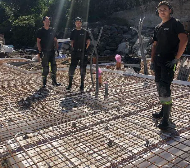
Slab reinforcement is a mesh and may be formed from two sets of bars placed at right angles. The table below gives bar spacing data in the form of areas of steel per metre width for various bar diameters and spacings. Reinforcement in slabs consists of a large number bars both ways which need to be tied together to form a mat. This is actually an expensive operation (see cost of fixing reinforcement in Nigeria).
It is necessary to point out that the critical span in the analysis of solid slabs is the short span. Therefore, the main reinforcements will lie parallel to the short span, and that is where you check your deflections (see why short spans are critical in floor slabs).
Table 1: Area of reinforcement per metre width of spacing
| Spacing | ϕ8 mm | ϕ10 mm | ϕ12 mm | ϕ16 mm | ϕ20 mm |
| 100 | 502 | 785 | 1130 | 2010 | 3141 |
| 125 | 402 | 628 | 904 | 1608 | 2513 |
| 150 | 335 | 523 | 753 | 1340 | 2094 |
| 175 | 287 | 448 | 646 | 1148 | 1795 |
| 200 | 251 | 392 | 565 | 1005 | 1570 |
| 225 | 223 | 349 | 502 | 893 | 1396 |
| 250 | 201 | 314 | 452 | 804 | 1256 |
| 275 | 182 | 285 | 411 | 731 | 1142 |
| 300 | 167 | 261 | 376 | 670 | 1047 |
For instance, if the area of reinforcement required (As,req) from calculation is 523 mm2/m, you can provide H12@200 c/c (Area of steel provided As,prov = 565 mm2/m).
(e) Crack Control
According to Clause 9.3.1.1(3) of Eurocode 2, if h is the total depth of the slab, then the maximum spacing of reinforcements is normally restricted to;
- 3h ≤ 400 mm for principal reinforcement
- 3.5 h ≤ 450 for secondary reinforcement
However, in areas of maximum moment, maximum spacing is restricted to;
- 2h ≤ 250 mm for principal reinforcement
- 3 h ≤ 400 mm for secondary reinforcement
For slabs 200 mm thick or greater the bar size and spacing should be limited to control the crack width and reference should be made to section 7.3.3 of the Eurocode 2.
(f) Curtailment of bars in slabs
Curtailment of bars is done according to the moment envelope. However, clause 9.3.1.2(1) requires that half the calculated span reinforcement must continue up to support. It is further stated that in monolithic construction, where partial fixity occurs along an edge of a slab but is not taken into account, the top reinforcement should be capable of resisting at least 25 percent of the maximum moment in the adjacent span and this reinforcement should extend at least 0.2 times the length of the adjacent span measured from the face of the support.

The above situation occurs in the case of simply supported slabs or the end support of a continuous slab cast integral with an L-beam which has been taken as a simple support for analysis but the end of the slab might not be permitted to rotate freely as assumed. Hence negative moments may arise and cause cracking.
(g) Shear capacity of slabs
Under normal loads, shear stresses are not critical and shear reinforcement is not required in floor slabs. Shear reinforcement is provided in heavily loaded thick slabs but should not be used in slabs less than 200 mm thick (clause 9.3.2 (1)). To check the shear capacity of slabs, the shear stress (vEd = VEd/bd) must be checked against the shear capacity of an unreinforced section (VRc,d). This is given by;
VRd,c = [CRd,c k(100ρ1 fck )1/3 + k1.σcp] ≥ (Vmin + k1.σcp)
Where;
CRd,c = 0.18/γc
k = 1 + √(200/d) < 0.02 (d in mm);
ρ1 = As1/bd < 0.02 (In which As1 is the area of tensile reinforcement which extends ≥ (lbd + d) beyond the section considered)
Vmin = 0.035k(3/2)fck0.5
K1 = 0.15; σcp = NEd/Ac < 0.2fcd
(Where NEd is the axial force at the section, Ac = cross sectional area of the concrete), fcd = design compressive strength of the concrete).
In a one-way slab, the design shear force is calculated from the support reactions or end-shears at the support, while in a two-way slab, they can be obtained from the coefficients in Table 3.15 of BS 8110-1:1997.
(h) Check for deflection
The check for deflection is a very important consideration in slab design and usually controls the slab depth. In normal cases, a strip of slab 1 m wide is checked against span-to-effective depth ratios. A slab should not deflect excessively under service load. Excessive deflection of slabs can cause cracking to partitions and finishes.
For deemed to satisfy basic span/effective depth (limiting to depth/250);
Actual L/d of the slab must be ≤ Limiting L/d × βs
The limiting basic span/ effective depth ratio is given by;
L/d = K [11 + 1.5√(fck)ρ0/ρ + 3.2√(fck) (ρ0/ρ – 1)1.5] if ρ ≤ ρ0
L/d = K [11 + 1.5√(fck) ρ0/(ρ – ρ’) + 1/12 √(fck) (ρ0/ρ)0.5 ] if ρ > ρ0
Where;
L/d is the limiting span/depth ratio
K = Factor to take into account different structural systems
ρ0 = reference reinforcement ratio = 10-3 √(fck)
ρ = Tension reinforcement ratio to resist moment due to design load
ρ’ = Compression reinforcement ratio
The value of K depends on the structural configuration of the member and relates the basic span/depth ratio of reinforced concrete members. This is given in the table 2;
Table 2: Basic span/effective depth ratio of different structural systems
| Structural System | K | Highly stressed ρ = 1.5% | Lightly stressed ρ = 0.5% |
| Simply supported slabs | 1.0 | 14 | 20 |
| End span of interior slabs | 1.3 | 18 | 26 |
| Interior span of continuous slabs | 1.5 | 20 | 30 |
| Flat slab | 1.2 | 17 | 24 |
| Cantilever slabs | 0.4 | 6 | 8 |
βs = (500As,prov)/(fykAs,req)
Two-way Spanning Slabs
Two-way action occurs when a slab is supported on all four sides. If the two dimensions and support conditions are the same, then the load is distributed to all supporting beams equally. In design, a slab is considered to be two-way if the ratio of the longer side to the shorter side is less than two.
For two way slabs, the precise amount and distribution of the load taken by each support, and consequently the magnitude of the bending moments on the slab, are not easily calculated if assumptions resembling real conditions are made. Therefore, approximate analyses are generally used. The method applicable in any particular case depends on the shape of the slab panel, the conditions of restraint at the supports and the type of load.
Two basic methods are commonly used to analyse slabs that span in two directions. They are;
- The theory of plates, which is based on elastic analysis, is particularly appropriate to the behaviour under service loads
- Yield-line theory, which considers the behaviour of the slab as a collapse condition approaches.
Generally, for rectangular slabs with standard edge conditions and subject to uniformly distributed loads, normally the bending moments are obtained using tabulated coefficients. These coefficients are based on elastic analysis from thin plate theory. The loads used in the analysis are factored to represent the ultimate limit state condition. This is the approach used in BS 8110 for slabs with corners that are not held down (no consideration for torsion). The analysis must take into account the support conditions which can be idealised as fixed, hinged, or free.
For slabs with irregular plan shapes and slabs subject to a combination of point loads and distributed loads, Johansen’s yield line analysis and the Hillerborg strip method provide powerful methods for strength calculations.
Simply supported two-way slabs
Where the corners of slabs are free to lift and no provision is made to resist forces at the corners, the maximum moments per unit width are given by the following expressions:
Msx = bending moment in strips with span lx = Msx = αsxqlx2
Msy = bending moment in strips with span ly = Msy = αsyqlx2
where lx is the shorter span of the panel, ly is the longer span of the panel and q is the design ultimate load per unit area. Values of αsx and αsy are given in Table 3.13 of BS 8110-1:1997 for different ratios of ly and lx, where ly is the longer span.
Rectangular panels with restrained edges
Where corners of a two-way slab are prevented from lifting and reinforced to resist torsion, the maximum bending moments per unit width are given by the following expressions:
Msx = βsxqlx2
Msy = βsyqlx2
where;
Msx is the maximum design moment either over supports or at midspan on strips with span lx
Msy is the maximum design moment either over supports or at midspan on strips with span ly
q is the design ultimate load per unit area,
lx is the shorter span, and
ly is the longer span
The coefficients can be obtained from Table 3.14 of BS 8110-1:1997.
Design Example of a two-way slab
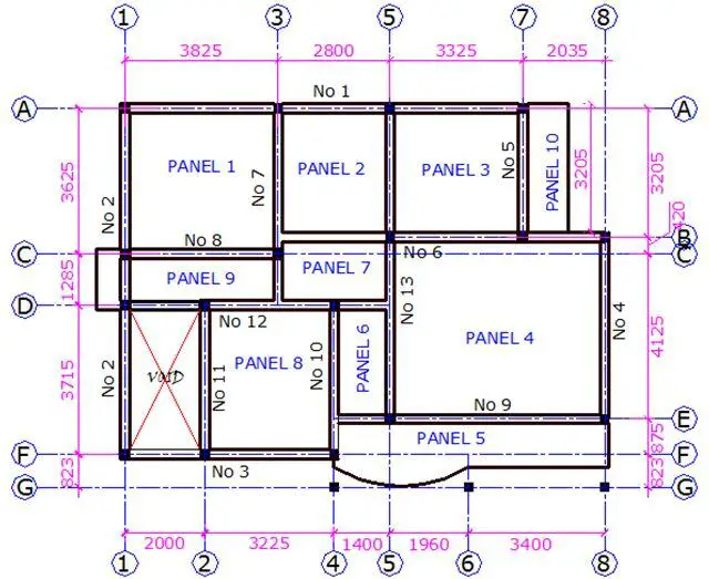
The general arrangement of the floor plan of a building is shown below. Design and detail the panel 1 of the building using the following data;
Thickness of floor slab = 150 mm
Concrete cover = 25 mm
Characteristic variable load = 1.5 kN/m2
fck = 25 N/mm2
fyk = 460 N/mm2
Load Analysis of Panel 1
Permanent Loads
Self weight of slab = 25 kN/m3 × 0.15m = 3.75 kN/m2
Weight of finishes = 1.2 kN/m2
Partition allowance = 1.5 kN/m2
Total dead load (gk) = 6.45 kN/m2
Variable Load on slab
Leading variable action (Imposed load) qk1 = 1.5 kN/m2
Total load on slab (ULS) = 1.35gk + 1.5qk = 1.35(6.45) + 1.5(1.5) = 10.9575 kN/m2
The floor slab (PANEL 1) is spanning in two directions, since the ratio (k) of the longer side (ly) to the shorter side (lx) is less than 2. Hence, k = Ly/Lx = 3.825/3.625 = 1.055 (say 1.1, however it is more appropriate to interpolate from the table).
Moment coefficient for two adjacent edges discontinuous
Short Span
Mid-span = 0.042
Continuous edge = 0.056
Long Span
Mid-span = 0.034
Continuous edge = 0.045
Design of short span
Mid span
MEd = αnlx2 = 0.042 × 10.9575 × 3.6252 = 6.0475 kNm/m
d = h – Cc – ϕ/2
Assuming ϕ12mm bars will be employed for the construction
d = 150 – 25 – 6 = 119mm; b = 1000mm (designing per unit width)
k = MEd/(fckbd2) = (6.0475 × 10⁶)/(25 × 1000 × 1192) = 0.0171
Since k < 0.167 No compression reinforcement required
z = d[0.5 + √(0.25 – 0.882k)]
z = d[0.5 + √(0.25 – 0.882 × 0.0273)] = 0.95d
As1 = MEd/(0.87fykz) = (6.0475 × 10⁶)/(0.87 × 460 × 0.95 × 119) = 133.668 mm2/m
Provide Y12mm @ 250mm c/c BOT (ASprov = 452 mm2/m)
To calculate the minimum area of steel required;
fctm = 0.3 × fck2⁄3 = 0.3 × 252⁄3 = 2.5649 N/mm2 (Table 3.1 EC2)
As,min = 0.26 × fctm/fyk × b × d = 0.26 × 2.5649/460 × 1000 × 144 = 208.76 mm2/m
Check if As,min < 0.0013 × b × d (187.2 mm2/m)
Since, As,min = 187.2 mm2, the provided reinforcement is adequate.
Check for deflection
We check for deflection at the short span of slabs
k = 1.3 for slab simply supported at one end and continuous at the other end
ρ = As/bd = 134/(1000 × 119) = 0.001126 < 10-3√fck (0.005)
Since ρ < ρ0
L/d = K [11 + 1.5√(fck ) ρ0/ρ + 3.2√(fck) (ρ0/ρ – 1)3⁄2]
L/d = 1.3 [11 + 1.5√(25) × 0.005/0.001126 + 3.2√25 (0.005/0.001126 – 1)3⁄2] = 1.3(44.3 + 102.106) = 190.327
Modification factor βs = 310/σs
σs = (310fykAs,req)/(500As,prov) = (310 × 460 × 133.688)/(500 × 452) = 84.341 N/mm2
βs = 310/84.342 = 3.67 > 2.0 (take 2.0)
Taking the distance between supports as the effective span, L = 3625mm
The allowable span/depth ratio = βs × 30.838 = 2.0 × 190.327 = 280.645
Actual deflection L/d = 3625/119 = 30.462
Since 280.645< 30.462 Therefore, deflection is ok.
Shear Verification
Maximum shear force coefficient for slab(β) = 0.44
VEd = βnlx
Ultimate shear force VEd = 0.44 × 10.9575 × 3.625 = 17.477 kN/m
VRd,c = [CRd,c.k. (100ρ1 fck)1/3
CRd,c = 0.18/γc = 0.18/1.5 = 0.12
k = 1 + √(200/d) = 1 + √(200/119) = 2.296 > 2.0, therefore, k = 2
ρ1 = As/bd = 452/(1000 × 119) = 0.003798 < 0.02; K1 = 0.15
VRd,c = [0.12 × 2 × (100 × 0.003798 × 25)1/3] × 1000 × 119 = 60476.947 N = 60.476 kN
Since VRd,c (60.476 kN) > VEd (17.477 kN), no shear reinforcement is required.
Note that shear reinforcements are rarely required in solid slabs supported by beams. Hence no further checks for shear will be done on the slab.
Design of short span
Continuous edge
MEd = αnlx2 = 0.056 × 10.9575 × 3.6252 = 8.0633 kNm/m
Using the procedure described above;
k = 0.0228; La/d = 0.95; As1 = 178.2236 mm2; As,min = 172.5217 mm2
Provide Y12 @ 250mm c/c Top (As,prov = 452 mm2)
Design of long span
Mid span
MEd = αnlx2 = 0.034 × 10.9575 × 3.6252 = 4.895 kNm/m
k = 0.0138; La/d = 0.95; As1 = 108.1945 mm2; As,min = 172.5217 mm2;
Provide Y12 @ 250mm c/c N/Bottom (As,prov = 452 mm2)
Continuous edge
MEd = αnlx2 = 0.045 × 10.9575 × 3.6252 = 6.479 kNm/m
k = 0.0183; La/d = 0.95; As1 = 143.2057 mm2; As,min = 172.5217 mm2;
Provide Y12 @ 250mm c/c Top (As,prov= 452 mm2)
Reinforcement Detailing
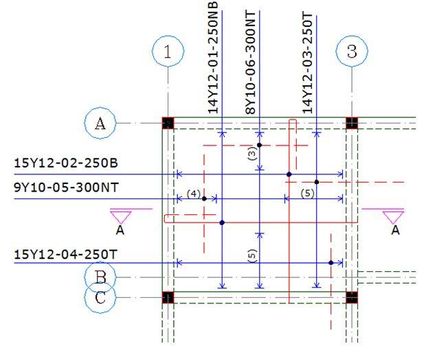
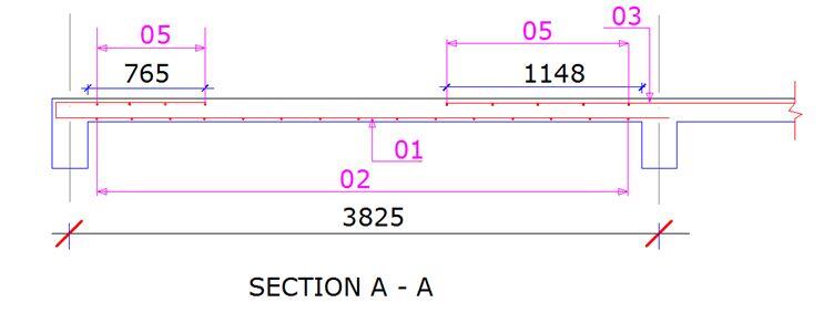




please allow it to be saved free
Very helpful and mostly well referenced. Deflection check is Clause 7.4.2 (2) of EC 2 1-1
Greetings Sabiiti, how can I check for Maximum area of steel
In what condition can we have an unrestrained slab?
The concrete cover of a septic tank whose side walls have been made with masonry.
Thank you Mr Ubani
Your teaching shows you have vast experience in this profession.
However something’s took me time to grab ( like that min[t;h])
Thank you!
Maybe making it clearer for newbies like us will go a long way in helping us
Thank you!
How did you get that 765 & 1148mm as the length of the bent bar and the top main bar respectively
At the discontinuous edge the length of Top Bar(T1) should be 20% of Lx while at the continuous edge the length is 20% of Lx
Engineers and other construction industry experts will find this post to be of great use as it provides insightful information about the design process for reinforced concrete slabs. It simplifies difficult structural engineering ideas into material that is clear and accessible to a broad audience.
Use of mesh steel can lead to more efficient use of resources and reduced waste, contributing to sustainable construction practices.
thanks alot sir
what is the case for panel 8?