It is common knowledge that a well-designed hollow steel section has lesser material weight and higher strength to weight ratio when compared with an equivalent open section profile such as a universal beam (I-section) or universal column (H-section). However, an important aspect of hollow steel section design is in the design of the connections. The design of hollow steel section connection in terms of joint resistance and cost fabrication is affected considerably by member sizing since the sections are usually welded to each other.
The most common types of hollow steel sections employed in design are;
- Circular hollow section (CHS)
- Square hollow section (SHS)
- Rectangular hollow section (RHS)
Joint Geometry
The most common types of hollow section joint configuration are;
- X-joints
- T- and Y-joints
- K- and N-joints with gap
- K- and N-joints with overlap
These configurations are shown in Figure 1.
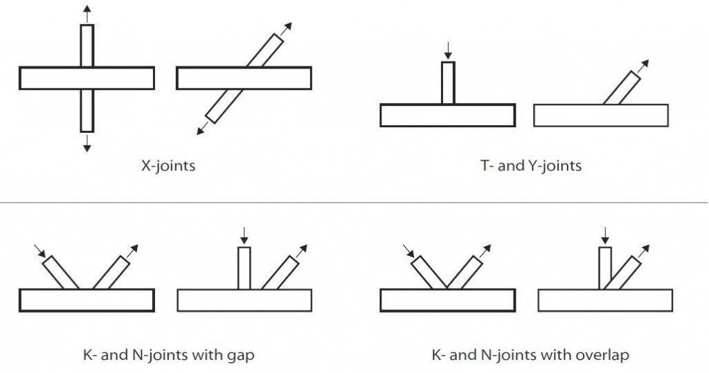
Generally, it is recommended that the angle between the chord and a bracing or between two bracings should be between 30° and 90° inclusive. If the angle is less than 30° then:
a) The designer must ensure that a structurally adequate weld can be made in the acute angle
b) The joint resistance calculation should be made using an angle of 30° instead of the actual angle
When K- or N-joints with overlapping bracings are being used, the overlap must be made with:
• Partial overlap where the first bracing runs through to the chord, and the second bracing sits on both the chord and the first bracing, or
• Sitting fully on the first bracing.
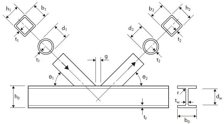
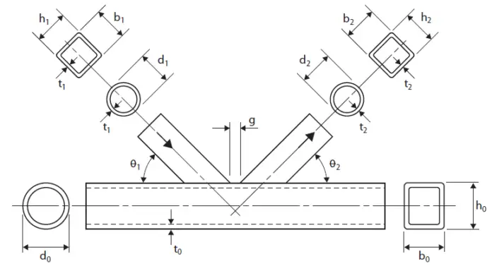
The typical joint geometry symbols used in the design are shown in Figure 2 and 3;

Multi-planar Joints
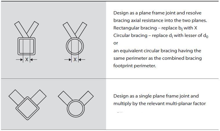
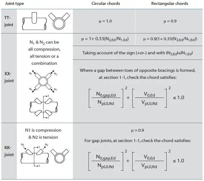
Multi-planar joints are typically found in triangular and box girders.To determine whether a joint should be considered as a multi-planar or a single planar joint refer to Figure 4. By applying the multiplanar factor, μ (Figure 5) to the calculated chord face deformation, you can use the same design formulae as planar joints.
The planar factors shown in the figure below have been determined for angles between the planes of 60° to 90°.
Welding of Hollow Steel Section Connections
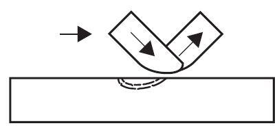
When a bracing member is under load, a non-uniform stress distribution is present in the bracing close to the joint, see Figure 6. Therefore, to allow for this non-uniformity of stress, the welds connecting the bracing to the chord must be designed to have sufficient resistance. Normally, the weld should be around the whole perimeter of the bracing using a buttweld, fillet-weld, or a combination of the two.
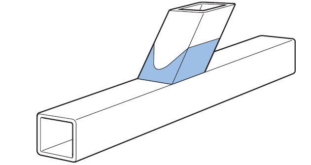
For bracing members in a lattice construction, the design resistance of a fillet-weld should not normally be less than the design resistance of the member. This is satisfied if the throat size (a) is at least equal to or larger than 1.1 times the width of the section, provided you use electrodes with an equivalent strength grade to the steel (both yield and tensile strength).
The weld resistance can also be verified from the simplified method for design of fillet weld EN 1993:1-8 clause 4.5.3.3;
Fw,Ed < Fw,Rd
Where;
Fw,Ed is the design value of the weld force per unit length
Fw,Rd is the design weld resistance per unit length
For a more efficient weld, you can use the directional method from EN 1993:1-8 clause 4.5.3.2.
Fabrication
In a lattice-type construction, the largest fabrication cost is the end preparation and welding of the bracings, and the smallest is the chords. As a general rule, the number of bracing members should be as small as possible. The best way to achieve this is using K- type bracings, rather than N-type bracings. Hollow sections are much more efficient in compression than open sections, angles or channels, meaning compression bracings do not need to be as short as possible. This makes the K-type bracing layout much more efficient.
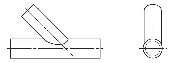
In circular chords, the ends of each bracing in a girder has to be profile-shaped to fit around the curvature of the chord member (see Figure 7), unless the bracing is very much smaller than the chord. Also, for overlap joints with circular bracings and chords, the overlapping bracing has to be profile shaped to fit to both chord and the overlapped bracing.
Joint Design Parameters and Resistance
The various geometric parameters of the joint have an effect on its resistance. This is dependant on the:
• joint type (single bracing, two bracings with a gap or an overlap) and,
• type of forces on the joint (tension, compression, moment).
The following points should be considered in the design of hollow steel section connections.
(1) The joint
(a) The joint resistance will always be higher if the thinner member sits on and is welded to the thicker member, rather than the other way around.
(b) Joints with overlapping bracings will generally have a higher resistance than joints with a gap between the bracings.
(c) The joint resistance, for all joint and load types (except fully overlapped joints), will be increased if small thick chords rather than larger and thinner chords are used.
(d) Joints with a gap between the bracings have a higher resistance if the bracing to chord width ratio is as high as possible. This means large thin bracings and small thick chords.
(e) Joints with partially overlapping bracings have a higher resistance if both the chord and the overlapped bracing are as small and thick as possible.
(f) Joints with fully overlapping bracings have a higher resistance if the overlapped bracing is as small and thick as possible. In this case, the chord has no effect on the joint resistance.
(g) On a size-for-size basis, joints with circular chords will have a higher resistance than joints with rectangular chords.
(2) The overall girder requirements
(a) The overall girder behaviour, e.g. lateral stability, is increased if the chord members are large and thin. This also increases the compression chord strut resistance, due to its larger radius of gyration.
(b) Consideration must also be given to the fabrication costs.
Joint Failure Modes
Joints have a number of different failure modes depending on the joint type, the geometric parameters of the joint and the type of loading. These various types of failure are described below;
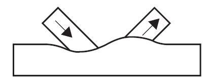
(a) Chord Face Failure
This is the most common failure mode for joints with a single bracing, and for K- and N-joints with a gap between the bracings if the bracing to chord width ratio (β) is less than 0.85.
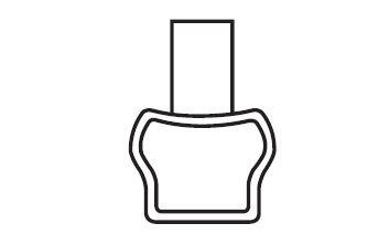
(b) Chord sidewall failure
This is the yielding, crushing, or instability (crippling or buckling) of the chord sidewall or web under the compression brace member. Also includes sidewall yielding if the bracing is in tension. Usually only occurs when the bracing to chord width ratio (β) ratio is greater than about 0.85, especially for joints with a single bracing.
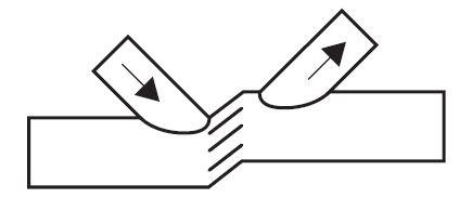
(c) Chord shear
This is found typically in the gap of a K-joint. The opposite vertical bracing force causes the chord to shear. It does not often become critical, but can if you use rectangular chords with the width (b0) greater than the depth (h0). If the validity limits are met then chord shear does not occur with circular chords.
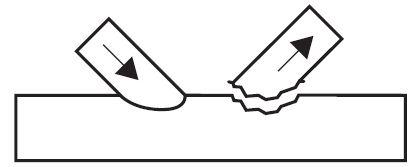
(d) Chord punching shear
This can be caused by a crack initiation in the chord face leading to rupture failure of the chord. It is not usually critical, but can occur when the chord width to thickness ratio (2γ) is small.
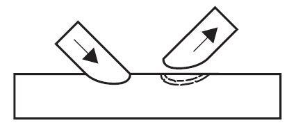
(e) Bracing Effective Width
This is non-uniform stress distribution in the brace causing a reduced effective brace width. This reduces the effective area carrying the bracing force. It is mainly associated with rectangular chord gap joints with large β ratios and thin chords. It is also the predominant failure mode for rectangular chord joints with overlapping rectangular bracings.
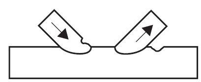
(f) Chord or bracing localised buckling
Due to the non-uniform stress distribution at the joint, reducing the effective area carrying the bracing forces. This failure mode will
not occur if the validity ranges are met.
(g) Shear of overlapping bracings
Due to the bracing’s horizontal force causing shearing at the chord face. This failure mode becomes critical for large overlaps, over 80% or 60%, depending on if the hidden toe of the overlapped bracing is welded to the chord.
Disclaimer:
The contents of this article are culled from;
TATA Steel: Design of welded joints Celsius®355 and Hybox®355







Your blog is very good
Hey you are doin agreat Job Keep it up!
i have one question for today …why is not possible to model composite slab/decks using RHS or other hollow box sections in etabs it only works for C and I sections?