A deep beam is a beam with a depth that is comparable to the span length. As a result, deep beam theory is required for the design of such elements due to the shear warping of the cross-section and a combination of diagonal and flexural tension strains in the body of a deep beam.
In BS 8110, the designer is directed to specialist literature for the design of beams with a clear span less than twice the effective depth. A deep beam is defined in Eurocode 2 (EN 1992-1-1:2004) as one whose effective span is less than three times its entire depth.
The fundamental principle underlying the design of slender beams is that stress distribution across the section is proportional to the distance from the bending’s neutral axis, i.e. plane sections of the cross-section of a beam perpendicular to its axis remain plane after the beam is bent. However, this notion only applies to deep beams to a limited extent, resulting in designs that are often not conservative.
For beams with short span-to-depth ratios, section warpage is important, and the smaller the span-to-depth ratio, the more apparent the deviation from the linear stress theory. For beams with span-to-depth ratios less than 2.5, the divergence from the fundamental linear stress hypothesis should be considered. The load is carried to the supports via a compression force that combines the load and the reaction, according to deep beam theory.
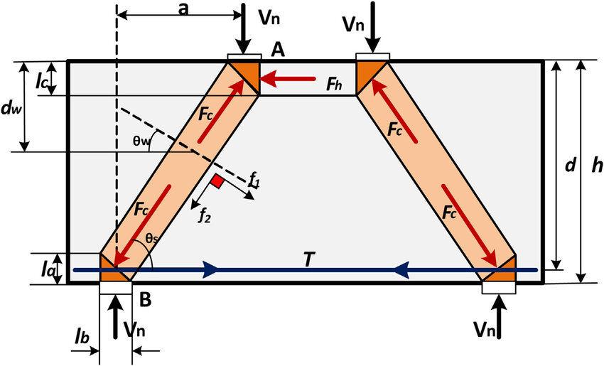
By implication, when compared to pure bending, the strain distribution in deep beams is no longer regarded linear, and shear deformations become prominent. Many countries have included design rules for these aspects in their design regulations as a result of the knowledge that a deep beam behaves differently from a slender beam.
The structural behaviour of a single-span deep beam after the concrete in tension has cracked is similar to that of a tied arch (Reynolds et al, 2008). The compression force at the centre of the arch rises from the support to a height at the crown equal to roughly half the beam’s span. Because the bending moment and the lever arm vary similarly along the length of the beam, the tension force in the tie is essentially constant along its length. The structural behaviour of a continuous deep beam is similar to that of a separate tied arch system for each span, paired with a suspension system centred over each internal support.
For deep beam reinforcement and detailing, Eurocode 2 recommends using one of two design techniques. The first methodology is connected to the strut-and-tie model application and the second methodology is related to a linear elastic analysis using the finite element method.
Strut and Tie Method (STM) for Deep Beams
Strut and Tie Modelling is an effective way of representing complex stress patterns as triangulated models. STM is based on the truss analogy concept and can be applied to numerous concrete structural parts. Essentially, strut-and-tie models (STM) are trusses consisting of struts, ties and nodes. It is commonly used to design non-standard concrete construction elements or parts of elements like pile caps, corbels, deep beams (depth > span/3), beams with holes, connections, and so on, where typical beam theory doesn’t always apply.
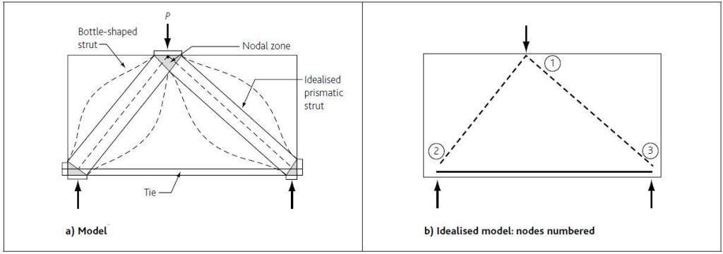
STM is a lower bound plastic theory, which implies it is safe as long as the following conditions are met:
- The equilibrium has been satisfied
- The structure is sufficiently ductile to allow the struts and connections to form.
- Struts and ties are proportioned to withstand the forces they are designed to withstand.
The strut-and-tie model design method can be broken down into four stages:
- Define and isolate the B- and D-regions
- Develop an STM – a truss system to represent the stress flow through the D-region and calculate the member forces in the truss
- Dimension and design the STM members, as well as the truss members, to resist the design forces.
- Iterate as needed to optimise the STM to reduce strain energy.
Note: B (or beam or Bernoulli) regions in which plane sections remain plane and design is based on ‘normal’ beam theory. D (or discontinuity or disturbed) regions in which plane sections do not remain plane; so ‘normal’ beam theory may be considered inappropriate. D-regions arise as a result of discontinuities in loading or geometry and can be designed using STMs. Typical examples of D-regions include connections between beams and columns, corbels, openings in beams, deep beams and pile caps, etc.
For more information on strut and tie models, see ‘How to design concrete members using strut-and-tie models in accordance with Eurocode 2‘.
Worked Example on Deep Beam Design
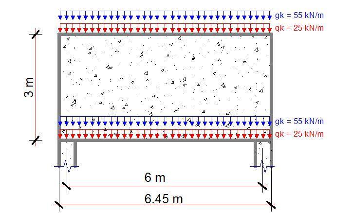
A 6450 x 3000 beam, 225 mm thick is supported on 450 x 225 columns. As shown below, it spans 6.0 m and supports actions of gk = 55 kN/m and qk = 25 kN/m at the top and bottom of the beam. Assume C25/30 concrete, fyk = 500 MPa and cnom = 30 mm.
Solution
Bottle-shaped Strut and tie model
At ULS, a strut and tie model may be constructed to determine strut-and-tie forces: see Figure below. Here the UDLs top and bottom are resolved into two-point loads applied at ¼ spans at the top of the wall.
Total applied load = [2 × ( 55 × 1.35 + 25 × 1.5 )] = 223.5 kN/m × 6.45m = 1441.575 kN
Self weight = [3.0 × 0.225 × 25 × 1.35] × 6.45 = 146.939 kN
Total = 1588.51 kN (say 2 × 795 kN)
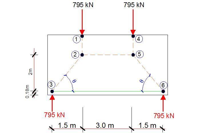
MC90 gives z = 0.6-0.7 × minimum (h, L) = 0.67 × 3000 = 2000 mm
MC90 gives u ≈ 0.12 × minimum (h, L) = 0.12 × 3000 = 360 mm (i.e 180 mm to centreline)
Check θ
tan θ = 2000/1500 = 1.33 i.e. < 2/1 ∴ OK
θ = 53.13o
Forces
C12 = 795 kN
Length of C23 = (20002 + 15002)0.5 = 2500 mm
By trigonometry:
C23 = (2500/2000) × 795 = 993.75 kN
T35 = (1500/2500) × 993.75 = 596.25 kN
Choice
A fan-shaped stress field is appropriate for the ULS but not necessarily for the SLS where the lever arm can be determined from elastic analysis or alternatively in accordance with the recommendations of MC90. Designed reinforcement will not be required if the design bearing stress is less than σRdmax = 0.85υ’fcd: in that case the design loads will be safely transmitted to the supports through the fan-shaped stress field. Suspension reinforcement is required to transmit the bottom loading to the top of the beam. In addition, minimal horizontal reinforcement is required for crack control.
Check (fan) strut at node 3
Strut in bearing, C32
For CCT Node (and fan-shaped strut)
σRdmax = 0.85υ’fcd
where
υ’ = 1 – fck/250 = 1 – (25/250) = 0.90
fcd = αccfck/γm = 0.85 × 25 / 1.5 = 14.2
σRdmax = 10.8 MPa
σEd32 = Fc / ab
where
Fc = 993.75 kN
a = width of strut = (acol – cnom – 2so) sin 53.13 + u cos 53.13
= (450 – 30 + 2 × (30 + say 12 + 30/2)) sin 53.13 + 360 cos 53.13
= (450 – 144) sin 53.13 + 360 cos 53.13 = 532.799 mm
b = thickness = 225 mm
σEd32 = 993.75 × 10³ / (532.799 × 225) = 8.289 MPa
i.e. < 10.8 MPa ∴ OK
NB: As σEd32 < σRdmax no further checks on strut 2-3 are necessary since the stress field is fan-shaped at the ULS.
Ties
a) Main tie
As,req = Ft / fyd = 596.25 × 10³ / (500 / 1.15) = 1371 mm2
Try 8H16 (1608 mm2)
Check anchorage:
Assuming straight bar
lbd = αlbrqd = α(ϕ/4) (σsd/fbd)
where
α = 1.0 (assumed)
ϕ = diameter of bar = 16 mm
σsd= 500 / 1.15 = 435 MPa
fbd = 2.25η1fctk / γm = 2.25 × 1.0 × 1.0 × (1.8 / 1.5) = 2.7 MPa
lbd = 1.0 x (16/4) × (435/2.7) = 644 mm
Average length available = 450 – 30 + cot 53.13° × (360 / 2) = 555 mm – no good
lbd = 644 x 1371/1608 = 549 mm: OK
∴ Provide 8H16 (1608 mm2)
Vertical tie steel
Vertical tie steel is required to take loads from bottom level to top level.
As,req = (55 x 1.35 + 25 × 1.5) / (500/1.15) = 111.75 × 10³ / ( 434.783) = 257 mm2/m
Minimum areas of reinforcement
Consider as a wall
Asvmin = 0.002Ac = 0.002 × 1000 × 225 = 450 mm2/m
Vertically, say minimum area and tie steel additive. Therefore provide
257 + 450 mm2/m = 707 mm2/m
Consider as a deep beam
Asdb,min = 0.2% Ac each surface: i.e. require 675 mm2/m
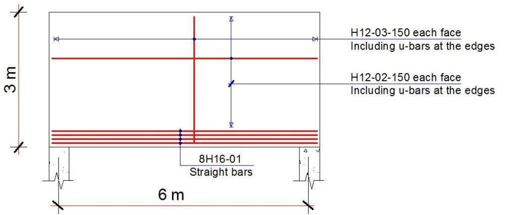
∴ Use H12@150 between each face (753 mm2/m each way each side)
Detailing Sketches
References
[1] Goodchild, C. H., Morrison, J., and Vollum, R. L. (2014): Strut-and-tie models: How to design concrete members using strut-and-tie models in accordance with Eurocode 2. The Concrete Centre, UK
[2] Hanoon, A. N., Jaafar, M. S., Hejazi F., and Abd Aziz F.N.A. (2016): Strut effectiveness factor for reinforced concrete deep beams under dynamic loading conditions, Case Studies in Structural Engineering, (6): 84-102, https://doi.org/10.1016/j.csse.2016.08.001.
[3] Reynolds C. E., Steedman J. C., and Threlfall A. J. (2008): Reynolds’s Reinforced Concrete Designer’s Handbook (11th Edition). Taylor and Francis

