When an overhead electric travelling crane is operating in a workshop or warehouse, a dynamic effect on the wheels is created as a result of a sudden drop of a full load, a slide of the sling, or a sudden braking action during the trip of a fully-loaded crane (where the load includes the crane’s self-weight). This consequently increases the static wheel load of the crane.
This effect is determined by multiplying the static wheel load by an impact factor to obtain the dynamic wheel load. Thus, maximum dynamic vertical wheel load = static wheel load × dynamic factor (ϕ).
The dynamic factor varies according to the crane’s duty class (loading class). The various loading classes are listed in Table 1. Table 2 lists the loads and dynamic parameters that should be addressed as part of a single crane motion. The values of the dynamic factors ϕi should be calculated using the formulae presented in Table 3.
Table 1: Recommendations for loading classes (based on Table B.1 in Eurocode 1, Part 3)a
| Item | Type of crane | Hoisting Class | S-Class |
| 1 | Hand-operated cranes | HC1 | S0, S1 |
| 2 | Assembly cranes | HC1, HC2 | S0, S1 |
| 3 | Powerhouse cranes | HC1 | S1, S2 |
| 4 | Storage cranes with intermittent operation | HC2 | S4 |
| 5 | Storage cranes and spreader bar cranes, with continuous operation | HC3, HC4 | S6, S7 |
| 6 | Workshop cranes | H2, H3 | S3, S4 |
| 7 | Overhead travelling cranes and ram cranes, |with grab and magnet operation | HC3, HC4 | S6, S7 |
| 8 | Casting cranes | HC2, HC3 | S6, S7 |
| 9 | Soaking-pit cranes | HC3, HC4 | S7, S8 |
| 10 | Stripper cranes, charging cranes | HC4 | S8, S9 |
| 11 | Forging cranes | HC4 | S6, S7 |
Table 2: Groups of loads and dynamic factors to be considered as one characteristic crane
action (based on Table 2.2 of Eurocode 1, Part 3)a
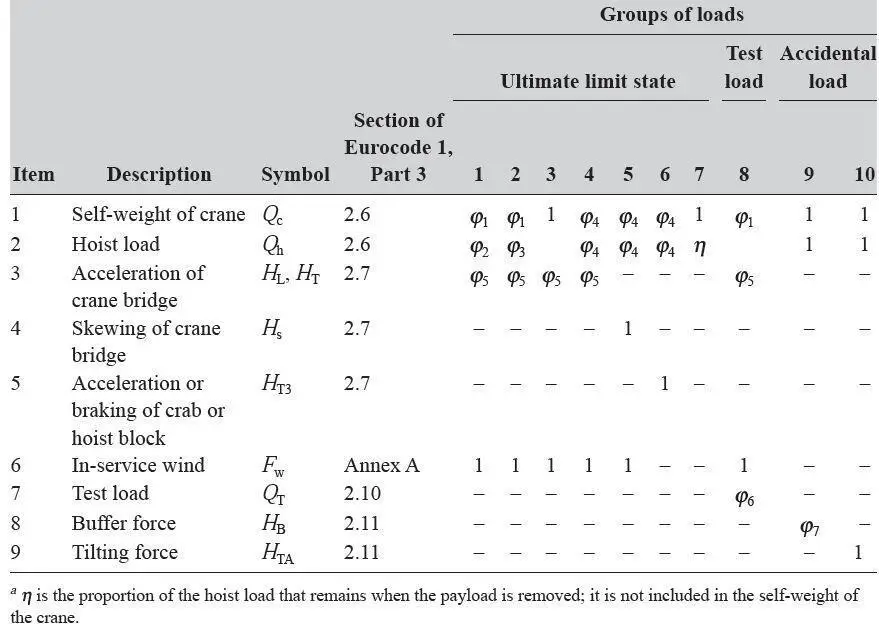
Table 3: Dynamic factors ϕi for vertical loads (based on Table 2.4 of Eurocode 1, Part 3)
| Dynamic factor ϕi | Value of dynamic factor |
| ϕ1 | 0.9 < ϕ1 < 1.1 The two values 1.1 and 0.9 reflect the upper and lower values of vibrational pulses |
| ϕ2 | ϕ2 = ϕ2,min + β2vh, where vh = steady hoisting speed in m/s For ϕ2,min and β2, see Table 4 |
| ϕ3 | ϕ3 = 1 − △m (1 + β3)/m, where △m = released or dropped part of the hoisting mass, m = total hoisting mass, β3 = 0.5 for cranes equipped with grabs or similar slow-release devices, and β3 = 1.0 for cranes equipped with magnets or similar rapid-release devices. |
| ϕ4 | ϕ4 = 1.0 provided that the tolerances for rail tracks as specified in EN 1993-6 are observed |
Table 4: Values of β2 and ϕ2,min (based on Table 2.5 of Eurocode 1, Part 3)
| Hoisting class of appliance | β2 | ϕ2,min |
| HC1 | 0.17 | 1.05 |
| HC2 | 0.34 | 1.10 |
| HC3 | 0.51 | 1.15 |
| HC4 | 0.68 | 1.2 |
Example
The vertical dynamic factors can be evaluated as follows.
For hoisting classes HC1and HC2, for example, referring to Table 3, we have the dynamic factor ϕ1 for vertical loads: 0.9 < ϕ1 < 1.1. Assume ϕ1 = 0.9, the lower value for vibrational pulses. We also have;
ϕ2 = ϕ2,min + β2vh
where ϕ2,min = 1.05 and β2 = 0.17 for hoisting class HC1, and ϕ2,min = 1.1 and β2 = 0.34 for hoisting class HC2 (see Table 2.4).
In addition, Vb = steady hoisting speed = 1.3 m/s (assumed).
Therefore
for class HC1: dynamic factor = ϕ2 = 1.05 + 0.17 × 1.3 = 1.27;
for class HC2: dynamic factor = ϕ2 = 1.1 + 0.34 × 1.3 = 1.54.
Thus, referring to Table 2.2 and assuming the group of loads 1, we have the following:
for class HC1: ϕ = ϕ1ϕ2 = 0.9 × 1.27 = 1.14;
for class HC2: ϕ = ϕ1ϕ2 = 0.9 × 1.54 = 1.38.
The following vertical dynamic factors may be used as guidance for various hoisting classes:
- For hoisting class HC1, light-duty hand-operated cranes, assembly cranes, powerhouse cranes, and intermittently used storage cranes: dynamic factor ϕ = 1.1 (minimum) to 1.25.
- For hoisting class HC2, medium-duty cranes (normally in factories, workshops, and warehouses, and for casting and in scrapyards with continuous operation): dynamic factor ϕ = 1.25 to 1.4.
- For hoisting class HC3, heavy-duty cranes (in foundries and for intermittent grab and magnet work, forging, charging etc.): dynamic factor ϕ = 1.4 (minimum).
Generally, the crane manufacturer will provide the dynamic factor along with the crane wheel loads when details of the duty (class), the span of the crane, and the lifting capacity are given to the manufacturer.
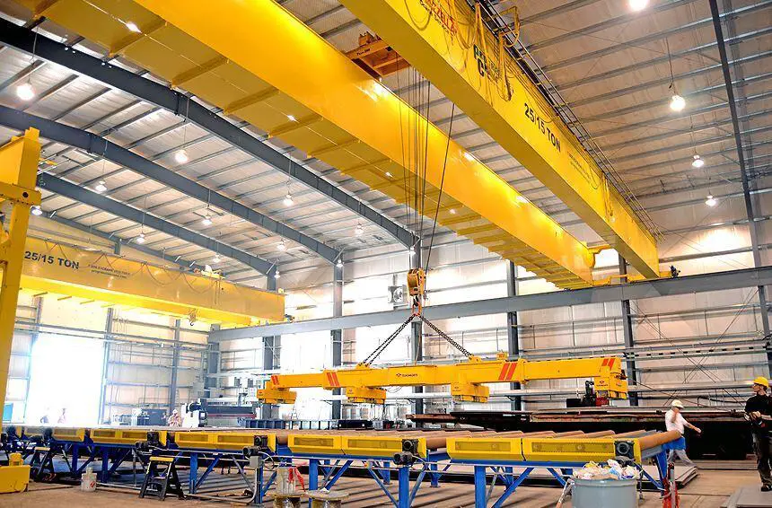
Transverse Horizontal Force (surge) on a Crane Girder
The following elements contribute to the transverse horizontal surge:
Thrust caused by the crab motor’s brakes being applied suddenly, causing the crab and cargo to come to a halt while traversing the crab girders. The frictional force created between the crab wheels and crab girders resists this thrust, which is then transferred to the crane’s crosshead girders and lastly transferred as point loads through the crane’s main wheels into the top flange of the crane girders.
Weights are frequently dragged across the manufacturing floor by a crane. This pulling motion creates a transverse horizontal component of force (a point load) on the crane girders through the crane wheels if the weight is particularly heavy. The crane girders receive the transverse horizontal force created by either of the above reasons or a combination of both through the double-flanged crane wheels on the end carriages, and cranes are intended to avoid derailment. It is difficult to quantify the value of this force because there are unknown components in addition to the preceding facts. The horizontal transverse force on each gantry girder must equal 10% of the load lifted, according to American specifications.
The British code of practice BS 2573-1: 1983 (British Standards Institution, 1983) specifies the following:
Value of total transverse horizontal force = 1/10 × weight of (lift load + crab). Eurocode 1, Part 3 stipulates the same value. Therefore value of total transverse horizontal force = 1/10 × weight of (lift load + crab).
This force should be shared equally between the two gantry girders.
Longitudinal horizontal force
The rapid application of brakes during crane travel causes frictional resistance to the locked wheels sliding along a rail attached to the gantry girder. This frictional resistance provides a horizontal force down the length of the gantry girder, which then transmits to the gantry girder’s supporting columns. Assume that steel sliding on steel has a coefficient of friction of 0.2. Consider the gantry girder’s maximum vertical wheel load, which happens when the weight lifted is at the closest allowed point to the girder.
So, maximum wheel load on the nearest gantry girder = maximum reaction from crane (load lifted + half the dead weight of crane) = W = R.
For example, if the load lifted is W1, the self-weight of the crane is W2, the distance of the load lifted from the nearest gantry girder is l and the crane span (centre to centre of crosshead) is L, then;
Maximum on-wheel load = W1(L − 1)/L + W2/2 = W = R.
Therefore longitudinal horizontal force developed = Rμ = 0.2R.
The American code of practice specifies that the longitudinal force is equal to 10% of the maximum wheel load. The British code of practice BS 2573 specifies that the longitudinal force is equal to 5% of the maximum wheel load, assumed to be acting on one gantry girder nearest to the load lifted. Eurocode 1 stipulates that the longitudinal force applied to the gantry girder should be calculated as follows (the equation numbers given in this chapter refer to Eurocode 1, Part 3):
HL,i = ϕ5Ki/nr
where
nr = number of gantry girders = 2
K = driving force (the value should be provided by the crane supplier),
ϕ5 = dynamic factor (see Table 5),
i = integer to identify the gantry girder (i = 1, 2).
Table 5: Dynamic factor ϕ5 (based on Table 2.6 of Eurocode 1, Part 3)
| Value of the dynamic factor ϕ5 | Specific use |
| ϕ5 = 1 | For centrifugal forces |
| 1.0 ≤ ϕ5 ≤ 1.5 | For systems where forces change smoothly |
| 1.5 ≤ ϕ5 ≤ 2.0 | For cases where sudden changes can occur |
| ϕ5 = 3.0 | For drives with considerable backlash |

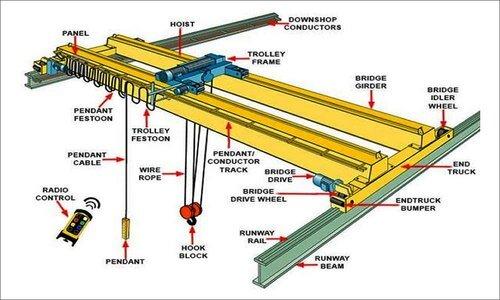




I am trying to select a beam and column sizes for a 32ton overhead workshop crane. Should I assume that the whole weight is acting on one column or how does one go about selecting the column size…