Overhead cranes are usually required in industrial or storage buildings for the lifting and/or movement of heavy loads from one point to another. These overhead cranes can be manually operated (MOT) or electrically operated (EOT). A Gantry girder may therefore be defined as a structural beam section, with or without an additional plate or channel connected to the top flange to carry overhead electric travelling cranes.
The typical components of an overhead travelling crane are shown in the figure below;
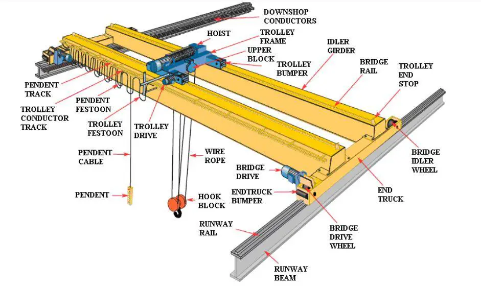
Crane gantry girders are usually designed to resist unsymmetrical forces and moments from vertical loads and reactions, horizontal forces, longitudinal forces, fatigue, and impact forces. The design of a gantry crane girder, therefore, involves the selection of a suitable and workable steel model and section to satisfy the machine (crane) requirements, loading, equipment, etc without leading to any structural or service failure.
Normally, for medium-duty (say 25 to 30 t capacity) cranes, standard universal rolled I-beams are used. In the design of gantry girders with long spans supporting heavy vertical dynamic crane wheel loads with transverse horizontal crane surges, the standard universal rolled beam section is not adequate as a gantry girder; the built-up section of a plate girder is adopted instead.
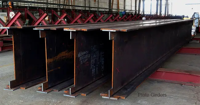
Gantry girders are usually subjected to very high vertical impacts, transverse horizontal surges, and longitudinal horizontal surges depending on their lifting capacity and geometry.
The transverse horizontal force generated either of the two following factors or by a combination both of it;
- Thrust from sudden application of the brakes of the crab motor, causing abrupt stoppage of the crab and load when transversing the crab girders. This thrust is resisted by the frictional force developed between the crab wheels and crab girders, is then transferred to the crosshead girders of the crane, and finally transferred as point loads through the main wheels of the crane into the top flange of the crane girders.
- A crane often drags weights across the shop floor. If the weight is very heavy, this pulling action induces a transverse horizontal component of force ( a point load) on the crane girders through the crane wheels.
This transverse horizontal force will be transferred to the crane girders through the double-flanged crane wheels on the end carriages and the crane is designed to avoid the possibility of derailment. Due to the difficulties in determining this kind of force, the horizontal transverse force on each gantry girder is equal to 10% of the total load lifted.
Furthermore, during the traveling of the crane, the sudden application of brakes induces frictional resistance to the sliding of the locked wheels upon a rail fixed to the gantry girder. This frictional resistance, in turn, generates a horizontal force along the length of the gantry girder and finally transfers to the columns that support the gantry girder. This is usually the source of the longitudinal horizontal force.
Gantry girders may be simply supported or continuous over supports. Continuity over supports reduces the depth and cost, but any differential settlement of the supports may reverse the original design values of the moments in the sections, thus exceeding the allowable stress in the material, with consequent collapse of the member. So, we adopt simply supported gantry girders, particularly for very heavily loaded girders.
Design Example of a Gantry Crane Girder
Design a gantry to satisfy the manufacturer’s design data given below;
Crane capacity = 20 tonnes (200 kN)
Maximum load lifted = 200 kN.
Crane span = 13.0 m
Weight of crane bridge = 120 kN
Spacing of wheels = 1.2 m
End clearance of crane = 600 mm (minimum).
Minimum headroom from rail top = 4500 mm.
Weight of crab = (1/5 of maximum load lifted + 5 kN) = (1/5) × 200 + 5 = 45 kN.
Crane and Girder Details
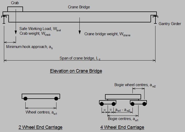
Crane details
Self weight of crane bridge (excluding crab); Wcrane = 120.0 kN
Self weight of crab; Wcrab = 25.0 kN
Crane safe working load (SWL); Wswl = 200.0 kN
Span of crane bridge; Lc = 13000 mm
Minimum hook approach; ah = 600 mm
No. of wheels per end carriage; Nw = 2
End carriage wheel centres; aw1 = 3000 mm
Class of crane; Q3
No. of rails resisting crane surge force; Nr = 1
Self weight of crane rail; wr = 0.5 kN/m
Height of crane rail; hr = 100 mm
Gantry girder details
Span of gantry girder; L = 5000 mm
Gantry girder section type; Plain ‘I’ section
Gantry girder ‘I’ beam; UB 610x305x238
Grade of steel; S 275
Loading, Shear forces and Bending Moments
Unfactored self weight and crane rail UDL
Beam and crane rail self weight udl; wsw = (Massbm × gacc) + wr = 2.8 kN/m
Maximum unfactored static vertical wheel load
From hook load; Wh = Wswl × (Lc – ah)/(Lc × Nw) = 95.4 kN
From crane self weight (including crab); Ws = [Wcrane/2 + Wcrab × (Lc – ah)/Lc]/Nw = 41.9 kN
Total unfactored static vertical wheel load; Wstat = Wh + Ws = 137.3 kN
Maximum unfactored dynamic vertical wheel load
From BS2573:Part 1:1983 – Table 4
Dynamic factor with crane stationary; Fsta = 1.30;
Dynamic wheel load with crane stationary; Wsta = (Fsta × Wh) + Ws = 165.9 kN
Dynamic factor with crane moving; Fmov = 1.25;
Dynamic wheel load with crane moving; Wmov = Fmov × Wstat = 171.6 kN
Max unfactored dynamic vertical wheel load;Wdyn = max(Wsta, Wmov) = 171.6 kN
Dynamic vertical wheel loads
Unfactored transverse surge wheel load
Number of rails resisting surge; Nr = 1
Proportion of crab and SWL acting as surge load; Fsur = 10 %
Unfactored transverse surge load per wheel; Wsur = Fsur × (Wcrab + Wswl)/(Nw × Nr) = 11.3 kN
Surge wheel loads
Unfactored transverse crabbing wheel load
Unfactored transverse crabbing load per wheel; Wcra = max(Lc × Wdyn/(40 × aw1), Wdyn/20) = 18.6 kN
Unfactored longitudinal braking load
Proportion of static wheel load acting as braking load; Fbra = 5 %
Unfactored longitudinal braking load per rail; Wbra = Fbra × Wstat × Nw = 13.7 kN
Ultimate loads
Load Case 1 (1.4 Dead + 1.6 Vertical Crane)
Vertical wheel load; Wvult1 = 1.6 × Wdyn = 274.6 kN
Gantry girder self weight udl; wswult = 1.4 × wsw = 4.0 kN/m
Load Case 2 (1.4 Dead + 1.4 Vertical Crane + 1.4 Horizontal Crane)
Vertical wheel load; Wvult2 = 1.4 × Wdyn = 240.3 kN
Gantry girder self weight udl; wswult = 1.4 × wsw = 4.0 kN/m
Horizontal wheel load (surge); Wsurult = 1.4 × Wsur = 15.7 kN
Horizontal wheel load (crabbing); Wcrault = 1.4 × Wcra = 26.0 kN
Maximum ultimate vertical shear force
From load case 1; Vv = Wvult1 × (2 – aw1/L) + wswult × L/2 = 394.4 kN
Ultimate horizontal shear forces (load case 2 only)
Shear due to surge; Vsur = Wsurult × (2 – aw1/L) = 22.0 kN
Shear due to crabbing; Vcra = Wcrault = 26.0 kN
Maximum horizontal shear force; Vh = max(Vsur, Vcra) = 26.0 kN
Ultimate vertical bending moments and co-existing shear forces
Bending moment loadcase 1; Mv1 = Wvult1 × L/4 + wswult × L2/8 = 355.7 kNm
Co-existing shear force; Vv1 = Wvult1/2 = 137.3 kN
Bending moment loadcase 2; Mv2 = Wvult2 × L/4 + wswult × L2/8 = 312.8 kNm
Co-existing shear force; Vv2 = Wvult2/2 = 120.1 kN
Ultimate horizontal bending moments (loadcase 2 only)
Surge moment; Msur = Wsurult × L/4 = 19.7 kNm
Crabbing moment; Mcra = Wcrault × L/4 = 32.5 kNm
Maximum horizontal moment; Mh = max(Msur, Mcra) = 32.5 kNm
Section Properties
Beam section properties
Area; Abm = 303.3 cm2
Second moment of area about major axis; Ixxbm = 209471 cm4
Second moment of area about minor axis; Iyybm = 15837 cm4
Torsion constant; Jbm = 785.2 cm4
Section properties of top flange only
Elastic modulus; Ztf = Tbm × Bbm2/6 = 507.5 cm3
Plastic modulus; Stf = Tbm × Bbm2/4 = 761.2 cm3
Steel design strength
From BS5950-1:2000 – Table 9
Flange design strength (T = 31.4 mm); pyf = 265 N/mm2
Web design strength (t = 18.4 mm); pyw = 265 N/mm2
Overall design strength; py = min(pyf, pyw) = 265 N/mm2
Section classification (cl. 3.5.2)
Parameter epsilon; ε = (275/py)1/2 = 1.019;
Flange (outstand element of comp. flange);ratio1 = Bbm/(2 × Tbm) = 4.959;
Web (neutral axis at mid-depth); ratio2 = dbm/tbm = 29.348;
Flange Classification = Class 1 plastic;
Web Classification = Class 1 plastic;
Overall Section Classification = Class 1 plastic
Shear buckling check (cl. 4.2.3)
Ratio d/t; d/t = dbm/tbm = 29.348;
PASS – d/t ≤ 70ε – The web is not susceptible to shear buckling
Design Checks
Vertical shear capacity (cl. 4.2.3)
Vertical shear capacity of beam web; Pvv = 0.6 × py × tbm × Dbm = 1860.1 kN
UF1 = Vv/Pvv = 0.212
PASS – Vv ≤ Pvv – Vertical shear capacity adequate (UF1 = 0.212)
Loadcase 1 – Vv1 ≤ 0.6Pvv – Beam is in low shear at position of max moment
Loadcase 2 – Vv2 ≤ 0.6Pvv – Beam is in low shear at position of max moment
Horizontal shear capacity (cl. 4.2.3)
Horizontal shear capacity of beam flange; Pvh = 0.6 × py × 0.9 × Tbm × Bbm = 1399.2 kN
UF2 = Vh/Pvh = 0.019
PASS – Vh ≤ Pvh – Horizontal shear capacity adequate (UF2 = 0.019 – low shear)
Vertical bending capacity (cl. 4.2.5)
Vertical bending capacity of beam;
Mcxz = 1.2 × py × Zxxbm = 2095.4 kNm
Mcxs = py × Sxxbm = 1983.8 kNm
Mcx = min(Mcxz, Mcxs) = 1983.8 kNm
UF3 = Mv1/Mcx = 0.179
PASS – Mv1 ≤ Mcx – Vertical moment capacity adequate (UF3 = 0.179)
Effective length for buckling moment (Table 13)
Length factor for end 1; KL1 = 1.00
Length factor for end 2; KL2 = 1.00
Depth factor for end 1; KD1 = 0.00
Depth factor for end 2;KD2 = 0.00
Effective length;Le = L × (KL1 + KL2)/2 + Dbm × (KD1 + KD2)/2 = 5000 mm
Lateral torsional buckling capacity (Annex B.2.1, 2.2 & 2.3)
Slenderness ratio; λ = Le/ryybm = 69.2;
Slenderness factor; v = 1/[1 + 0.05 × (λ/xbm)2]0.25 = 0.899;
Section is class 1 plastic therefore; βw = 1.0
Equivalent slenderness; λLT = ubm × v × l × √(βw) = 55.1;
Robertson constant; αLT = 7.0
Limiting equivalent slenderness; λL0 = 0.4 × (p2 × ES5950/py)0.5 = 35.0;
Perry factor; ηLT = max(αLT × (λLT – λL0)/1000, 0) = 0.141;
Euler buckling stress; pE = π2 × ES5950/λLT2 = 665.5 N/mm2
Factor phi; ϕLT = [py + (ηLT + 1) × pE]/2 = 512.3 N/mm2
Bending strength; pb = pE × py/[ϕLT + (ϕLT2 – pE × py)0.5] = 218.9 N/mm2
Buckling resistance moment; Mb = pb × Sxxbm = 1638.8 kNm
Equivalent uniform moment factor; mLT = 1.0
Allowable buckling moment; Mballow = Mb/mLT = 1638.8 kNm
UF4 = Mv1/Mballow = 0.217
PASS – Mv1 ≤ Mballow – Buckling moment capacity adequate (UF4 = 0.217)
Horizontal bending capacity (loadcase 2 only) cl. 4.2.5
Horizontal moment capacity of top flange; Mctf = min(py × Stf,1.2 × py × Ztf) = 161.4 kNm
UF5 = Mh/Mctf = 0.202
PASS – Mh ≤ Mctf – Horizontal moment capacity adequate (UF5 = 0.202)
Combined vertical and horizontal bending (loadcase 2 only)
Cross section capacity (cl. 4.8.3.2)
Section utilisation; UF6 = Mv2/Mcx + Mh/Mctf = 0.359;
PASS – Section capacity adequate (UF6 = 0.359)
Member buckling resistance (cl. 4.8.3.3.1)
Uniform moment factors;
mx = 1.0
my = 1.0
Case 1; UF7 = mx × Mv2/(py × Zxxbm) + my × Mh/(py × Ztf) = 0.421;
Case 2; UF8 = mLT × Mv2/Mb + my × Mh/(py × Ztf) = 0.433;
PASS – Buckling capacity adequate (UF7&8 = 0.433)
Check beam web bearing under concentrated wheel loads (cl. 4.5.2.1)
End location
Maximum ultimate wheel load; Wvult1 = 274.6 kN
Stiff bearing length (dispersal through rail); b1 = hr = 100 mm
Bearing capacity of unstiffened web; Pbw = [b1 + 2 × (Tbm + rbm)] × tbm × py = 954.7 kN
UF9 = Wvult1/Pbw = 0.288
PASS – Wvult1 ≤ Pbw – Web bearing capacity adequate (UF9 = 0.288);
Check beam web buckling under concentrated wheel loads (cl. 4.5.3.1)
End location – top flange not effectively restrained rotationally or laterally
Maximum ultimate wheel load; Wvult1 = 274.6 kN
Stiff bearing length (dispersal through rail); b1 = hr = 100 mm
Effective length of web; LEweb = 1.2 × dbm = 648 mm
Buckling capacity of unstiffened web;
Pxr = 1/2 × 25 × ε × tbm/[(b1 + 2 × (Tbm + rbm)) × dbm]1/2 × 0.7 × dbm/LEweb × Pbw
Pxr = 401.3 kN
UF10 = Wvult1/Pxr = 0.684
PASS – Wvult1 ≤ Pxr – Web buckling capacity adequate (UF10 = 0.684)
Allowable deflections
Allowable vertical deflection = span/600; dvallow = L/limitv = 8.3 mm
Allowable horizontal deflection = span/500; dhallow = L/limith = 10.0 mm
Calculated vertical deflections
Modulus of elasticity;E = ES5950 = 205 kN/mm2
Due to self weight; dsw = 5 × wsw × L4/(384 × E × Ixxbm) = 0.1 mm
Due to wheels at position of maximum moment;
dv1 = Wstat × L3/(48 × E × Ixxbm) = 0.8 mm
Total vertical deflection; dv = dsw + dv1 = 0.9 mm
PASS – dv ≤ dvallow – Vertical deflection acceptable (Actual deflection = span/5641)
Calculated horizontal deflection
Due to surge (wheels at position of max moment); dhs = Wsur × L3/(48 × E × Iyybm/2) = 1.8 mm
Horizontal crabbing deflection; dhc = Wcra × L3/(48 × E × Iyybm/2) = 3.0 mm
Maximum horizontal deflection;
dh = max(dhs, dhc) = 3.0 mm
PASS – dh ≤ dhallow – Horizontal deflection acceptable (Actual deflection = span/1676)
.







I am going for wood products engineering in ui and the world seems me to be a dullard and a wood worker…What can I do to be encouraged
How can I possess the good books from this Site free of charge?
Regards,
Amon Mwale