Arches are important structural elements in engineering that provide economical solutions in buildings and bridges. Three-hinged arch structures are pinned at the supports (springings) and somewhere along the barrel, which is usually at the crown. The structural analysis and design of three-hinged arches involve the determination of the internal stresses (bending moment, shear force, axial force, and torsion in the structure due to externally applied load, and providing adequate sections to resist the applied load.
In horizontal beams supporting uniformly distributed load, the bending moment increases with the square of the span and hence they become uneconomical for long-span structures. In such situations, arches could be advantageously employed, since they would develop horizontal reactions, which in turn reduce the bending moment.
A three-hinged arch, which is usually made from steel or timber, is statically determinate. Unlike statically indeterminate arches, they are not affected by differential settlement or temperature changes. Three-hinged arch structures have three natural hinges as the name implies. The two supports are hinged, and another internal hinge is usually located at the crown.
A three-hinged arch has four unknown reactions, i.e., two vertical reactions and two horizontal reactions at the supports. For their determination, three equilibrium equations can be formulated considering the whole of the structure.
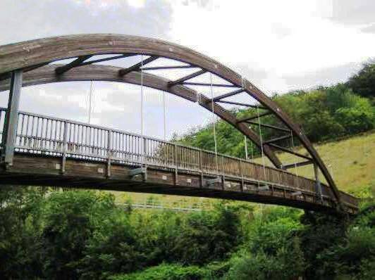
Since it is well known that the bending moment at any internal hinge is zero, the internal hinge in the barrel of the arch provides an additional equation for the equilibrium of any part of the system. This means that the sum of the moments of all external forces, which are located on the right (or on the left) part of the structure with respect to the internal hinge is zero. Therefore, a three-hinged arch is a geometrically unchangeable and statically determinate structure. The figure below shows a three-hinged Bolt-laminated Ekki Timber bridge at Finowfurt, Germany.
The peculiar feature of arched structures is that horizontal reactions are induced even when the structure is subjected to vertical load only. These horizontal reactions under vertical loading Ax = Bx = H are called the thrust of the structure. At any cross-section of the arch, bending moments, shear, and axial forces are developed. However, the bending moments and shear forces are smaller than corresponding internal forces in a simply supported beam covering the same span and subjected to the same load.
This fundamental property of the arch is thanks to the thrust developed. Thrusts in both supports are pointed towards each other and consequently reduce the bending moments that would arise in beams of the same span and load configuration. The two parts of an arch may be connected by a tie. In this case in order for the structure to remain statically determinate, one of the supports of the arch should be supported on a roller.
Solved Example on Analysis of a Three-hinged Arch
For the parabolic arch that is loaded as shown below, compute the support reactions and plot the internal stresses diagram for the identified sections. The arch is hinged at points A, B, and C.
SOLUTION
Geometrical properties of the arch
The ordinate (y) at any point along a parabolic arch is given by;
y = [4yc (Lx – x2)] / L2
Where;
yc = Height of the crown of the arch from the base
L = Length of arch
x = Horizontal ordinate of interest
Hence, y = [4 × 10 (45x – x2)] / 452
The general equation of the arch now becomes;
y = (8/9)x – (8/405)x2 —————– (1)
Differentiating equation (1) with respect to x
dy/dx = y’ = (8/9) – (16/405)x —————— (2)
From trigonometric relations, we can verify that;
Sin θ = y’/[1 + (y’)2]0.5 —————- (3)
Cos θ = 1/[1+ (y’)2]0.5 —————- (4)
From the above relations, we can carry out the calculations for obtaining the geometrical properties of the arch structure.
Let us consider point A (support A of the structure);
We can verify that at point A, x = 0, and y = 0;
From equation (2) above, y’ = 8/9;
Thus,
Sin θ = (8/9)/[1 + (8/9)2]0.5 = 0.664
Cos θ = 1/[1 + (8/9)2]0.5 = 0.747
Similarly, let us consider point 3 of the structure;
At point 3, x = 27.5m
From equation (1), we can obtain the value of y as; y = [(8/9) × 27.5] – [(8/405) × 27.52] = 9.5061m;
The tangent at that point can be obtained from from equation (2); dy/dx = y’ = (8/9) – [(16/405) × 27.5] = – 0.1975
Thus,
Sin θ = (-0.1975)/[1 + (-0.1975)20.5 = -0.1937
Cos θ = 1/[1 + (-0.1975)2]0.5 = 0.9813
For the entire section, it is more convenient to set out the geometrical properties in a tabular form. See the picture below;
Support Reactions
Let ∑MB = 0; anticlockwise negative
(Ay × 45) – (12 × 22.5 × 33.75) – (25 × 10) – (15 × 6.913) = 0
Therefore, Ay = 210.36 kN
Let ∑MA = 0; clockwise negative
(By × 45) – (25 × 35) + (15 × 6.913) – (12 × 22.5 × 11.25) = 0
Therefore, By = 84.64 kN
Let ∑MCL = 0; anticlockwise negative
(Ay × 22.5) – (Ax × 10) – (12 × 22.5 × 11.25) = 0
22.5Ay – 10Ax = 3037.5 ——— (a)
Substituting, Ay = 210.36 kN into equation (a)
Hence, Ax = 169.56 kN
Let ∑MCR = 0; clockwise negative
(By × 22.5) – (Bx × 10) – (25 × 12.5) – (15 × 3.087) = 0
22.5By – 10Bx = 358.8 ——— (b)
Substituting, By = 84.64 kN into equation (b)
Hence, Bx = 154.56 kN
Internal Stresses
Bending Moment
MA = 0 (hinged support)
M1 = (210.36 × 7.5) – (169.56 × 5.555) – (12 × 7.5 × 3.75) = 298.294 kN.m
M2 = (210.36 × 15) – (169.56 × 8.889) – (12 × 15 × 7.5) = 298.181 kN.m
MC = (210.36 × 22.5) – (169.56 × 10.000) – (12 × 22.5 × 11.25) = 0
Coming from the right hand side;
MC = (84.64 × 22.5) – (154.56 × 10) – (25 × 12.5) – (15 × 3.087) = 0
M3 = (84.64 × 17.5) – (154.56 × 9.506) – (25 × 7.5) – (15 × 2.593) = -214.442 kN.m
M4 = (84.64 × 10) – (154.56 × 6.913) = -222.073 kN.m
MB = 0 (hinged support)
Shear
Q = ∑V cosθ – ∑H sinθ
QA = (210.36 × 0.747) – (169.56 × 0.664) = 44.551 kN
Q1 = [210.36 – (12 × 7.5)] 0.860 – (169.56 × 0.509) = 17.203 kN
Q2 = [210.36 – (12 × 15)] 0.959 – (169.56 × 0.284) = -19.040 kN
QCR = [210.36 – (12 × 22.5)] 1.000 – (169.56 × 0.000) = – 59.64 kN
Q3 = [210.36 – (12 × 22.5)] 0.981 – (169.56 × – 0.193) = – 25.782 kN
Q4L = [210.36 – (12 × 22.5)] 0.897 – (169.56 × – 0.443) = – 21.618 kN
Q4R = {[210.36 – (12 × 22.5) – 25] × 0.897} – [(169.56 – 15) × (- 0.443)] = 7.452 kN
QB = (- 84.64 × 0.747) – [154.56 × (- 0.664)] = 39.402 kN
Axial
N = -∑V sinθ – ∑H cosθ
NA = (-210.36 × 0.664) – (169.56 × 0.747) = – 266.340 kN
N1 = – [210.36 – (12 × 7.5)] 0.509 – (169.56 × 0.860) = – 207.085 kN
N2 = – [210.36 – (12 × 15)] 0.284 – (169.56 × 0.959) = -171.230 kN
NC = – [210.36 – (12 × 22.5)] 0.000 – (169.56 × 1.000) = -169.560 kN
N3 = -{[210.36 – (12 × 22.5)] × – 0.193} – (169.56 × 0.981) = -177.849 kN
N4L = -{[210.36 – (12 × 22.5)] × – 0.443} – (169.56 × 0.897) = – 178.516 kN
N4R = -{[210.36 – (12 × 22.5) – 25] × – 0.443} – [(169.56 – 15) × (0.897)] = – 176.136 kN
NA = – (-84.64 × – 0.664) – (154.56 × 0.747) = – 171.657 kN
Internal Stresses Diagram (Not to scale)
Like us on www.facebook.com/structville
Thank you for visiting.


Nice one. Thanks for the info
Thank you Engr.