The use of arches as a structural form can be dated back to antiquity. Arch structures are unique structural forms which resists forces majorly by converting them to compressive forces, in a process popularly referred to as arch action. By transferring the compressive forces through the arch rib or barrels, they are transferred to the base of the arch as outward thrusts, which implies that the final support of the arch must be stiff and stable. According to [1], the economic viability of any arch bridge depends on the suitability of the site’s geology and soil condition. This article aims to explore the analysis and design of a concrete arch bridges subjected to Load Model 1 of Eurocode, using Staad Pro software.
Historically, most arch bridges were associated with stone masonry, which later gave way to the use of bricks in the nineteenth century. These structures were designed to minimise the development of tensile stresses in the members, and hence often gave rise to very massive structures. However, with advances in materials such as concrete and steel, more slender and aesthetically pleasing structural forms can be achieved.

Arch bridges can be classified according to the following;
- Materials of construction
- Structural scheme, and
- Shape of arch
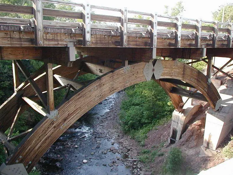
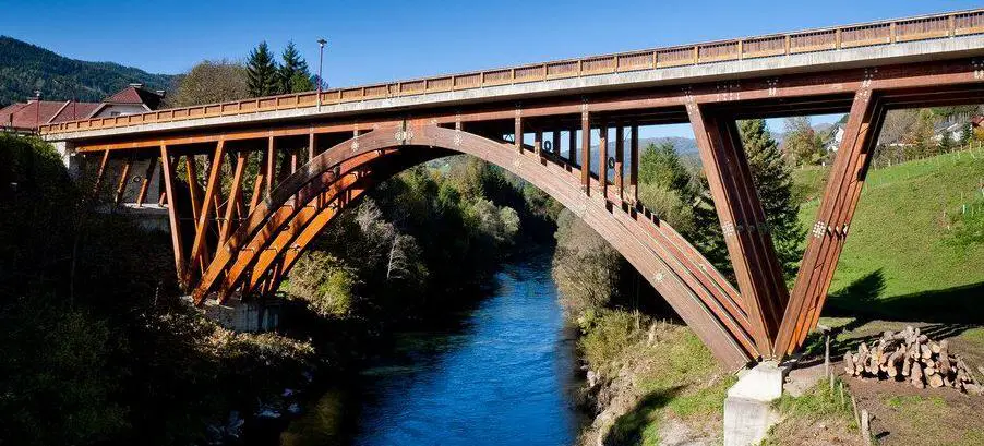
As far as materials is concerned, arch bridges can be constructed from timber, stone masonry, bricks, concrete, or steel. However, in recent times, timber bridges are usually restricted to small spans. An example of a timber arch bridge is the Mur River Bridge in Austria (also called the Holzeuropabrücke wood bridge) which is made of three-hinged parabolic timber. It is considered to be the largest cantilevered timber bridge in Europe. Also, the Eagle River Timber Bridge in Michigan is another example of three-hinged arch timber bridge with a span of about 23-24 metres. The Tynset Bridge in Norway built in the year 2001 is considered the longest timber bridge in the world designed for full highway loading with a span of 70 m. The structural form consists of tied timber truss arches supporting the bridge deck with the use of suspension cables.
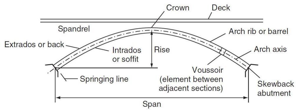
Reinforced concrete and steel arches are altogether much lighter structures than masonry arch bridges. The structure consists basically of the arch, the deck and usually some supports from the arch to the deck – in that order of importance. The basic parts of an arch bridge are;
- The deck
- The crown
- The spandrel
- The arch rib or barrel
- The springings
- The extrados or back
- The intrados or soffit
- The skewback or abutment
- The rise, and
- The span
These components are shown in the figure below;
Concrete arches can be made of full width curved arch, or series of ribs. Steel is usually made of series of ribs.
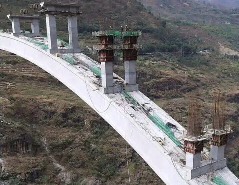

Steel arch bridges can be lower arch bridge or through trussed arch bridge.
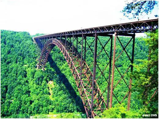
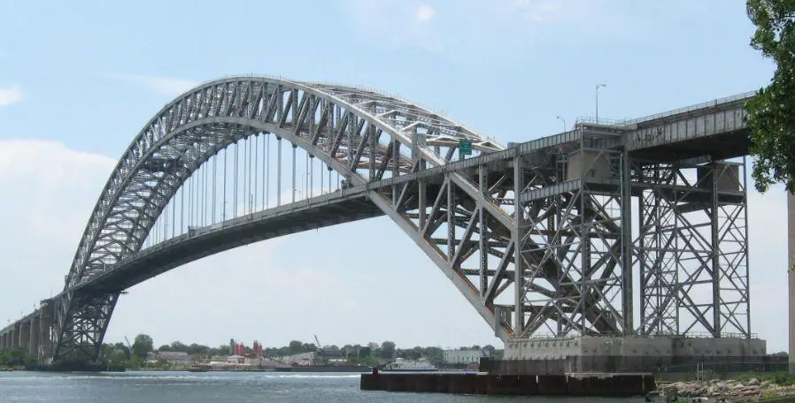
The structural scheme adopted in any arch bridge can be influenced by a lot of factors such as the type of deck, environmental conditions, cost, and feasibility. However in terms of structural form, arches can be broadly classified as hinged or fixed. A hinged arch can be two-hinged arch or three-hinged arch. While the former is statically indeterminate, the later is statically determinate. Statically determinate arch structures are free from secondary stresses from indirect actions such as differential settlement and temperature difference. An example of a three-hinged arch bridge is the Rossgraben Bridge in Switzerland.
In terms of shape, an arch bridge can be segmental (circular), parabolic, or elliptical. However, the parabolic arch is the most popular shape for arch bridges. According to [1], the ratio of span to rise should generally be in the range of 2:1 to 10:1. The flatter the arch the greater the horizontal thrust and this may affect the structural form selected, i.e. whether or not a tie should be introduced, or the stiffness of the deck relative to the arch.
Analysis of an arch bridge on Staad Pro
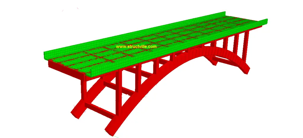
It is possible to model and analyse arch bridges using Staad Pro software. We are going to demonstrate this using a parabolic arch bridge. The general structural form of the bridge is shown below. The structural form can be said to be a bit similar to that of Krka River Bridge in Croatia.
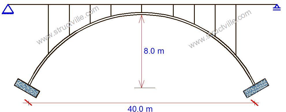
The equation of the parabolic arch bridge is given by;
y = 4x/5 – x2/50 ———– (1)
Using equation (1), the nodes for the vertical coordinates of the arch were established at 1m interval along the horizontal axis, and connected using linear line elements.
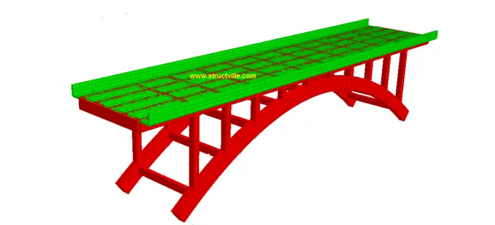
The arch is made of two ribs connected to each other with rigid reinforced concrete members along the axis of the arch and at the deck level. The arch ribs are made of concrete members 1500 mm deep, and 750 mm wide. The spandrels are made of concrete columns of dimensions 600 mm x 600 mm transferring the load of the bridge deck to the arch. The rendered structural form of the bridge deck is shown below;
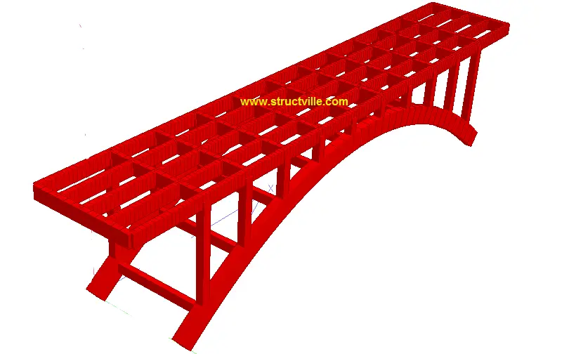
The longitudinal girders of the bridge deck are 5 in number with dimensions of 1000 mm x 400 mm, spaced at 2 m centre to centre. They are supported by transverse girders of the same dimension, which transfer the deck load to the columns. The columns (spandrels) ultimately transfer the deck load to the arch ribs. The deck slab is 200 mm thick and has a total width of 10.4 m. The vehicle carriage way is 8.0 m wide, with 1.2m cantilever on either side with raised kerbs for pedestrian walkway. The overall dimensions of the arch bridge is shown below.

The bridge deck has been subjected to Load Model 1 on 2 notional lanes, and a remaining area of 2 m. The tandem load system on the bridge was modelled as a moving load on Staad Pro. Hence, the loads considered on the arch bridge are the self weight, UDL traffic action, and wheel load traffic action.
The analysis results are as follows;
(1) Self weight
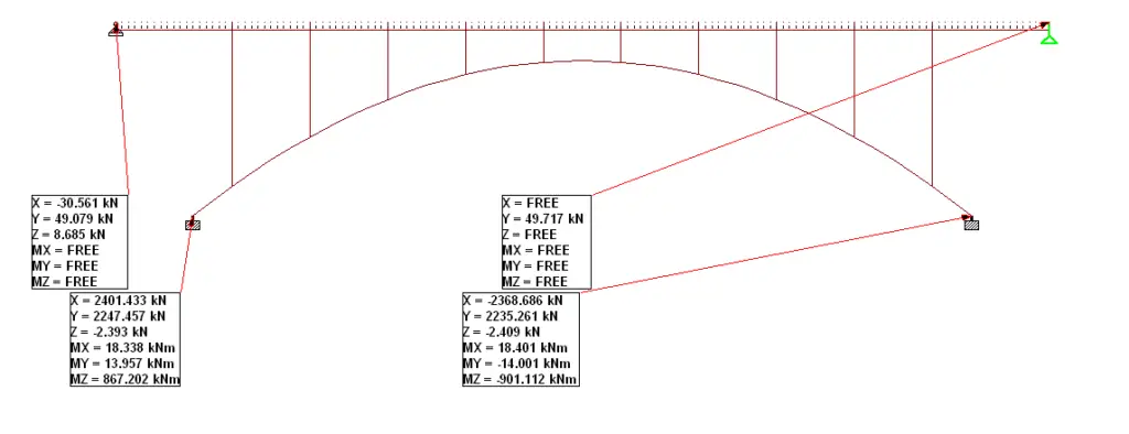

Maximum sagging moment in arch rib = 259 kNm
Maximum hogging moment in arch rib = 901 kNm
Maximum Bending moment in column (spandrel) = 138 kNm (4th column from the left)

Maximum shear force in arch rib = 359 kN
Maximum shear force in column (spandrel) = 101 kN (4th column from the left)

Maximum axial force in arch rib = 3276 kN (compression)
Maximum axial force in column (spandrel) = 501 kN (1st column from the left)
(2) Traffic UDL

Maximum sagging moment in arch rib = 82 kNm
Maximum hogging moment in arch rib = 222 kNm
Maximum Bending moment in column (spandrel) = 39.7 kNm (4th column from the left)

Maximum shear force in arch rib = 93 kN
Maximum shear force in column (spandrel) = 28.8 kN (4th column from the left)

Maximum axial force in arch rib = 855 kN (compression)
Maximum axial force in column (spandrel) = 160 kN (1st column from the left)
(3) Traffic Wheel Load
The variation of bending moment as wheel load travels through the bridge deck is shown below;


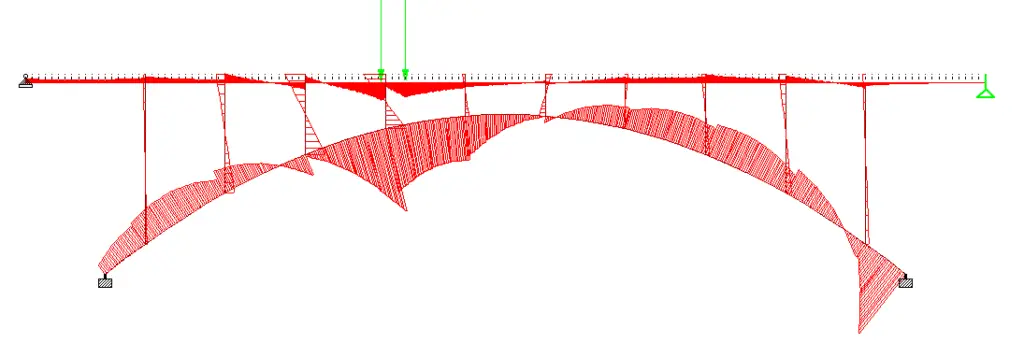
For moving traffic action;
Maximum hogging moment = 1593.285 kNm
Maximum sagging moment = 900.343 kNm
Maximum shear force = 646.233 kN
Maximum axial compression = 1414 kN
Maximum axial tension = 804.699 kN
There are other forces such as torsion that should be checked in the analysis result. For design purposes, the self weight and traffic actions can be combined using 1.35Gk + 1.5Qk. Other actions on bridges should also be considered.
Thank you for visiting Structville today, and God bless you. Remember to contact us for your structural designs, detailing, and project management and training. You can send an e-mail to ubani@structville.com or a whatsapp message to +2347053638996.
References
Melbourne C. (2008): Design of Arch Bridges. In ICE Manual of Bridge Design, Institution of Civil Engineers, UK



Thank you! I appreciate your work