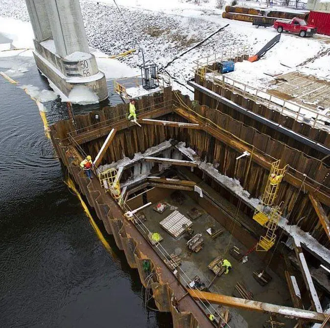
A cofferdam is a structure used to keep soil and/or water out of an area where construction work must be done to a depth below the surface. The effects of water penetration must always be taken into consideration in any calculations, even though the total exclusion of water is frequently unnecessary and occasionally not practicable.
The cofferdam should always be taken into consideration by the designer when constructing a basement. The use of steel sheet piles as the main permanent structural wall can result in significant time and cost savings. The wall can be built to support vertical loads and water tightness can be achieved by using the right sealing technique.
The use of top-down construction should be taken into consideration when controlling ground movement is a particular concern. This will prevent secondary movement from happening when the lateral soil loading is transferred from the temporary supports, as they are removed, to the permanent structure. It will also ensure that movement of the top of the wall is restricted with the introduction of support at ground level prior to the commencement of excavation.
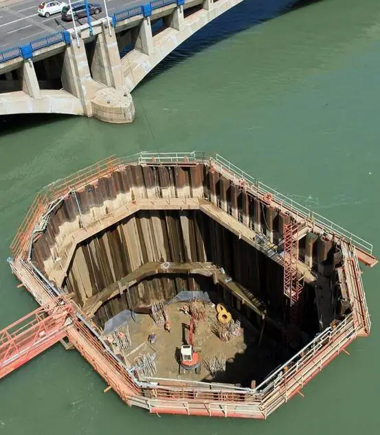
There are two main methods for designing cofferdams. Although single-skin structures are more frequently employed, double-wall or cellular gravity structures may be used for very large or deep excavations and marine works.
Requirements for a Cofferdam
The cofferdam’s design must adhere to the following requirements:
- The structure must be capable of withstanding all of the different loads applied on it.
- Pumping must be capable of controlling the amount of water entering the cofferdam.
- The formation level must be stable and not be prone to uncontrollable heaving, boiling, or piping at any stage of construction.
- The permanent structure or any other existing structure next to the cofferdam shall not be impacted by the deflection of the cofferdam walls and bracing.
- It must be demonstrated that overall stability exists in the face of out-of-balance earth forces brought on by sloping terrain or probable slip failure planes.
- The cofferdam needs to be the right size for the construction work that will be done inside of it.
- The construction of temporary cofferdams must be done in a way that allows for the greatest possible quantity of construction waste to be recycled.
Planning a Cofferdam
Before starting the design of a cofferdam, the designer must have a clear understanding of their goals. In order for the design to account for all the load situations related to the construction and takedown of the cofferdam, the sequence of construction operations must be established. The designer can find the key design instances from this sequence and then compute the minimal penetrations, bending moments, and shear forces necessary to establish the pile section and length.
The designer should conduct a risk assessment of the effects of any departure from the intended sequence as part of the analysis of the construction activities. These deviations could take the form of excessive excavation at any stage, a failure to reach the required piling penetration, the installation of the support at the incorrect level, or the imposition of a significant surcharge loading from construction equipment or materials.
The site management should be informed and contingency plans should be prepared to minimize any risk if any stage of the cofferdam construction is particularly fragile. This will reduce the likelihood that critical conditions will materialize.
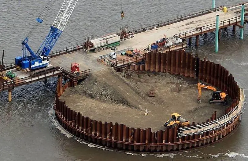
The bulk of cofferdams are built as temporary works, hence it might not be cost-effective to plan for every conceivable loading scenario. When evaluating the design instances, decisions will need to be made, typically including the site management. An example of this may be when evaluating the hydraulic loading on a cofferdam. Flood conditions are typically seasonal, therefore creating a cofferdam that will always keep water out may need a significant increase in pile size, strength, and construction.
The design philosophy may call for evacuating the cofferdam in a severe flood situation and letting it overtop and flood instead. Under these circumstances, the designer must account for overtopping, taking into account the impact of any trapped water on the stability after the flood subsides as well as the effect of the abrupt ingress of water on the base of the cofferdam.
The site area should be cleared before construction begins to make room for the installation of plant and guide frames. Excavation shouldn’t start until all the necessary machinery and supplies, including pumping equipment when needed, are on hand to support the piles.
The cofferdam and support frames should be checked when excavation is finished to make sure they are functioning as planned and to give as early a warning as possible of any safety-critical issues. In the UK, it is required by law to keep a written record of such monitoring, which is good practice.
Below are a few potential causes of failure, and it will be clear that many of them have to do with issues that could develop after the cofferdam is complete.
Common Causes of Cofferdam Failures
Cofferdam failure may have a variety of causes, but in reality, it is typically caused by one or more of the following:
- The structure’s installation and design lacked attention to detail.
- Failing to consider the range of probable water levels and conditions.
- Failing to compare facts learned during excavation with design calculations.
- Excessive excavation during any phase of the construction process.
- The amount and quality of the framework used to support the loads is insufficient.
- Loads on frame members that were not considered during the design, such as those caused by walkways, materials, pumps, and other structures supported by walings and struts.
- Accidental damage to structural components that are left unrepaired.
- Inadequate penetration to prevent heaving or pipework. Failure to take into account how pipes or heave will affect soil pressures.
- A breakdown in communication between the designers of permanent and temporary works, as well as between designers and site management or site management and workers.
In many circumstances, the occurrence of several of the aforementioned conditions at once might result in failure, even though any one of them might not have been enough to produce the failure on its own.
Design of Cofferdams
The ensuing remarks are especially pertinent to the design and construction of cofferdams. In order to choose the proper geotechnical parameters for the soils in which the cofferdam is to be built, the longevity of the cofferdam construction must be evaluated. Since the cofferdam is a temporary structure, total stress values can often be employed.
However, the designer must determine each clay’s susceptibility to the quick attainment of a drained condition and, if in doubt, should examine the final construction using effective stress parameters. Generally speaking, it is advised to use effective stress strength parameters when designing cofferdams that will be in use for three months or longer. It may be suitable to utilize effective stress criteria for considerably shorter periods of time since the existence of silt laminations or layers inside clays can quickly lead to the attainment of drained conditions.
The types of cofferdams to be discussed in this section are;
- single-skin cofferdams
- double skin/walled cofferdams
- Cellular cofferdams
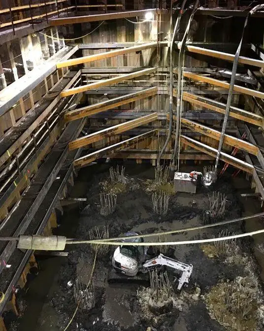
Single skin Cofferdams
Sheet piles that are either internally propped or externally anchored are generally used to create single skin cofferdams. Depending on the kind of soil, the piles will need to be driven to a level that will create enough passive resistance even though they are just intended to provide support between frames and below the lowest frame. If there are at least two frames, the wall will still be stable if the cut-off of the piles below the excavation is insufficient to give the required passive support, and the pile beneath the lowest frame can be thought of as a cantilever.
Nevertheless, this will result in significant stresses in the lowest frame and is to be avoided whenever possible. In every situation, the penetration below formation level must be sufficient to prevent water from entering the excavation.
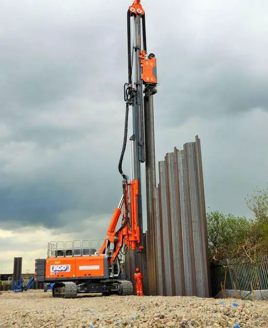
Records should be kept when driving to look for any signs of the piles declutching. To prevent seepage in such a situation, grouting may be required behind the piles. The same restrictions that apply to cantilever retaining walls apply to cantilever pile cofferdams as well, particularly in terms of the retained height that can be achieved. When the cofferdam has very wide plan dimensions but a modest depth, slanted struts or external anchorages are frequently more cost-effective to include. However, it should not be overlooked that space beyond the cofferdam area is needed for the installation of external anchorages, and wayleaves may be needed to place the anchors beneath neighbouring homes.
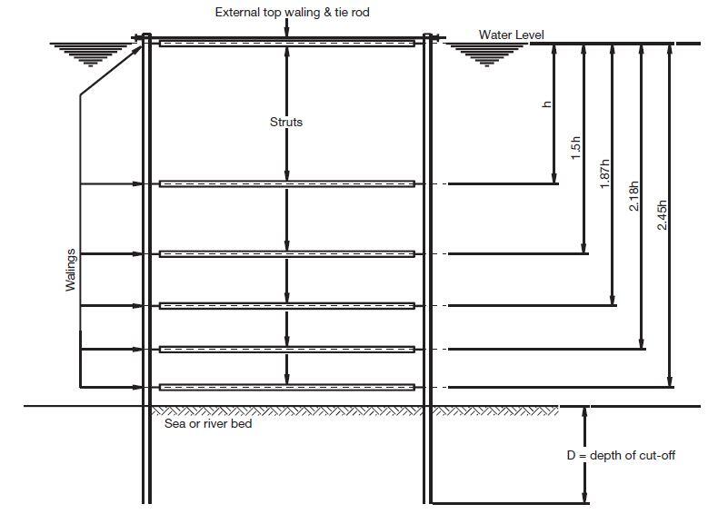
A system of internal frameworks in the form of steel sections or specialized bracing equipment is often used for a cofferdam with a depth of more than 3 meters. In order to accurately represent the construction process, the design should be carried out in stages. Excavation and dewatering to just below the top frame level would typically be followed by the installation of the first frame. This process would be repeated for each additional frame.
It should be noted that in the case of cofferdams submerged in water, the forces experienced during dewatering and frame installation may be significantly greater than those present in the finished cofferdam. It is recommended to use a specific interlock sealant for cofferdams in water. It is frequently more efficient to install all of the framing underwaters before beginning the dewatering process when a cofferdam is to be utilized exclusively for the purpose of excluding water and the depth of soil to be excavated is merely nominal.
The ideal frame spacing for this construction style is shown below. The spacing causes the second and succeeding frames to be loaded almost equally.
Walls/double skin Cofferdams
Double wall cofferdams are made up of two parallel lines of sheet piles that are joined at one or more levels by a network of steel tie rods and walings. Sand, gravel, or crushed rock are common granular materials used to fill the area between the walls. The outer line of piles serves as the anchorage, and the exposed or inner wall is intended to serve as an anchored retaining wall. For this type of construction, U or Z profile sheet piles are ideal.
The wall should be analyzed as a whole as a gravity structure, and it will typically be observed that the width should not be less than 0.8 of the retained height of water or soil in order to ensure acceptable factors of safety against overturning and sliding. It is advised that the logarithmic spiral approach developed by Jelinek be used to assess the structure’s overall stability.
Transverse bulkheads should be installed to create strong points at the ends and in the middle of the structure to facilitate construction and contain any potential damage. A square or rectangular cell tied in both directions may make up the strong points. Both within and outside of the construction, the water regime is crucial. Weepholes should be installed on the inner side of the building close to the bottom of the exposed piles to allow for unrestricted drainage of the fill material, lowering pressures on the inner wall and preventing the fill’s shear strength from deteriorating over time.
Weepholes are only useful for small constructions, and it’s not always practicable to drain the fill completely. If necessary, wellpoints and pumps give a speedy alternative for drainage. However, any water pressure acting on the piles should always be taken into consideration by the designer. It is crucial to avoid using clay or silt as fill material, and any of this kind that is found within the cofferdam and is above the primary foundation stratum must be removed before the fill is added.
The piles must be driven deep enough into the ground to produce the necessary passive resistance, which is below excavation or dredging level. Under these circumstances, the structure will lean toward the side that was excavated, and the lateral earth forces on the side that was retained may be regarded as active. The penetration of the piling must also be sufficient to control the effects of seepage when cohesionless soils are present at or below the excavation level. The structure’s weight and any additional loading should be compared to the founding stratum’s bearing capacity.
This type of cofferdam is inappropriate since there is rock at the excavation level unless:
• The type of the rock makes it possible to drive sheet piles into it deeply enough.
• Tie rods can be mounted at a low height (probably underwater).
• The piles can be positioned and grouted into a prepared trench in the rock.
• Dowels inserted into rock sockets can be used to pin the pile toes.
Base friction and gravity forces should be enough to prevent overturning and sliding if the piles are driven onto hard rock or to a nominal depth below the dredged level. Depending on the degree of deflection, the lateral earth pressure on the retained side will be somewhere between at rest and active in this situation.
Because of the uneven distribution of vertical stresses within the cofferdam (owing to moment effects), the internal soil pressures operating on the outside walls are likely to be greater than active, hence the design should be based on pressures that are 1.25 times the active values.
Cellular Cofferdams
Self-supporting gravity structures known as cellular cofferdams can be formed into a variety of designs utilizing straight web sheet piles. After being forced together, the piles form closed cells that are filled with cohesionless material. The circular cells are joined together using manufactured junction piles and brief arcs to achieve wall continuity.
They only need a small amount of penetration to be stable, provided the foundation material is solid. Pile penetration will help in the vulnerable period before the fill has been deposited and the cell has become intrinsically stable by assisting in the resistance of any lateral stresses that may arise during construction.
Cofferdams made of cells are used to hold back large amounts of water or later-placed fill. They are frequently used to create quay walls, breakwaters, and dock closure cofferdams. The straight web pile section, in particular the interlocks, has been created to resist the circumferential tension that forms in the cells as a result of the contained fill’s radial pressure while also allowing for enough angular deflection to allow for the formation of cells with a useful diameter.
The steel can be placed in cellular construction such that the maximum tensile resistance is created across the profile because no bending moments are developed in the sheet piles. Because of this, the sections have very limited bending strength and cannot be used to build standard straight sheet pile walls. Tie rods and walings are not necessary.

