The effect of water pressures on the soils at the formation level can have a negative impact on a cofferdam‘s stability to the point where collapse may happen. Excessively high water pressure in granular soils results in piping, whereas it causes heaving in cohesive or extremely densely packed soils.
When the pressure exerted on the soil grains by the water flowing upward is so great that the effective stress in the soil is close to zero, piping occurs. The soil in this circumstance lacks shear strength and transforms into a state that might be compared to quicksand, making it incapable of supporting any vertical weight. When this occurs, the cofferdam workers are obviously in a highly risky situation, and the soil’s passive resistance to the cofferdam wall will also be significantly reduced.
In extreme circumstances, this may result in the cofferdam failing and the wall losing all support. By constructing a flow net, an engineer may predict the chance of piping for a specific cross section and determine the exit hydraulic gradient. The factor of safety against piping will be revealed by comparing the estimated value to the critical hydraulic gradient; for clean sands, this should typically lie between 1.5 and 2.0.
When designing circular cofferdams and the corners of rectangular constructions, care should be taken because these situations present more of a three-dimensional challenge than a long wall would. Installing the sheet piles at a deeper depth increases the flow path and lowers the hydraulic gradient, enhancing the factor of safety against piping.
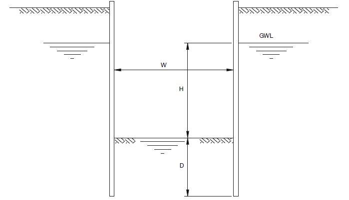
| Width of cofferdam (W) | Depth of cut-off (D) |
| 2H or more | 0.4H |
| H | 0.5H |
| 0.5H | 0.7H |
If the force of the water pressure acting on a block of material inside the cofferdam exceeds the bulk weight of the block, base heave may happen. This can happen in cohesive or very tightly packed granular material. Using a flow net, it is possible to determine the average water pressure acting on the line drawn between the piles and translate it to an uplift force acting on the soil plug inside the cofferdam in order to determine the likelihood of heave.
The groundwater level can be lowered using well points outside of the cofferdam to lessen the flow of water into the structure. As an alternative, pumping from well sites inside the cofferdam that is at or below pile toe level can minimize flow into the structure. However, it should be kept in mind that when a cofferdam’s stability or convenience of use depends on pumping, the dependability of the pumps is crucial, and backup capacity must be available to handle any problems.
Flow nets in Cofferdams
The construction of flow nets is a helpful tool because it gives the engineer a visual depiction of the soil’s flow regime and the ability to compute the water pressures in a specific situation. The following notes show how a net can be drawn given uniform soil conditions and permeability. The shape and complexity of a flow net depend on the homogeneity and permeability of the soil.
• A scaled cross-section drawing of the problem should be produced.
• A datum level should be marked on the cross-section either at an impermeable boundary or at a suitable level below the cofferdam.
• The flow criteria must be determined.
• External water level.
• Internal water level.
• Centre line of cofferdam (this is the axis of symmetry).
• Lines of flow must be parallel to the cofferdam walls and the impervious datum.
The net is created using flow lines and equipotential lines using the aforementioned guidelines (a standpipe at any point on an equipotential line would register the same height H above the datum level). These are roughly square-shaped and at right angles to one another. Trial and error is a big part of this procedure, but with practice, you’ll be able to construct the flow net reasonably quickly and accurately.
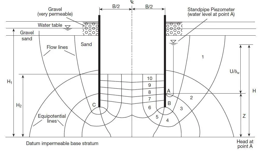
In order to determine the pore water pressure ‘u’ at any location (using the example above);
• Determine the probable head ‘H’ at the targeted location (note that the potential head drop is always the same between successive equipotential lines once a square net has been formed)
H = H1 – (H1 – H2) × n/Nd
where;
n = number of equipotential drops to the point being considered
Nd = total number of drops
Hence at point A,
H = H1 – (H1 – H2) × (2/10)
• At any point H = u/γw + z
where;
u = pore water pressure
γw = density of water
z = height of point above datum
As H, γw and z are known, u can be calculated;
u = (H – z) × γw
Flow nets can also be used to estimate the approximate volume of water flowing around the toes of the piles into the cofferdam. The flow volume ‘Q’ m3/s per metre run of wall is given by;
Q = k(H1 – H2) × Nf/Nd
where;
k = coefficient of permeability of the ground (m/s)
H1 – H2 = total head drop (m)
Nf = number of flow channels (in half width of cofferdam)
Nd = number of potential drops
The factor of safety against piping
The “exit hydraulic gradient” right below the formation level inside the cofferdam can be calculated using the flow net. The hydraulic gradient ‘i‘ (which is dimensionless), is the loss of head per unit length in the direction of flow. The exit gradient (ie) in the aforementioned case is represented by;
ie = [(H1 – H2)/Nd] × (2Nf/B)
Where;
B/2Nf is the width of each exit flow net square since B/2 is the half-width of the cofferdam
Nf is the number of flow channels in the half-width of the cofferdam
The critical hydraulic gradient at which piping takes place and the effective soil stress drops to zero for ground with a saturated bulk weight of around 20 kN/m3 is ic = 1.0. The factor of safety against piping is defined as;
FoS = ic/ie, which roughly equals (1.0/ie).
A flow net like the one used as an example is merely a section of a very long cofferdam. The 3-dimensional nature of the flow has the effect of further concentrating the head loss within the soil plug between the sheet pile walls for square or circular cofferdams. The head loss per field on the inside face of the cofferdam should be corrected using the following correction factors:
Circular cofferdams = parallel wall values x 1.3
In the corners of a square cofferdam = parallel wall values x 1.7
For clean sands, the factor of safety against piping (1.0/ie)should be between 1.5 and 2.0
Source: ArcelorMittal (2008): Piling handbook (8th Edition)

